Kinetrol Spring Return Units: Spiral Torsion Springs Are Key

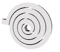
Spiral torsion spring
Simple view of spiral
torsion spring (protruding
tab and hex center
are loading points.)
Spiral torsion springs are found in many places - clocks, watches, timers ... and Kinetrol spring return units!

Capable of storing much more energy than a typical compression spring, and working in smaller, more compact packages, spiral torsion springs for valve and damper actuation are a proven step-up over helical compression springs.

When a torque is applied to a spiral torsion spring, an angular displacement is created between the first and second loading points, the coil deflects (tightens), and the spring material is placed under stress, exerting a linear (to the degree of rotation) rotational "output" torque,  which drives the spring's rotation. Practically speaking, spiral torsion springs allow for lower torque loss, lower torque stress, and much greater reliability for use in valve and damper actuation.
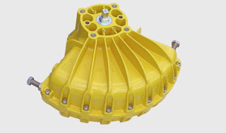
Kinetrol Spring Return
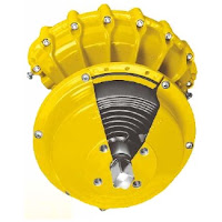
Kinetrol Spring Return Unit
(note cutaway revealing
spiral torsion spring.)
Along with the inherent advantages of spiral torsion springs, additional benefits of the Kinetrol spring return unit are:

  • Separate housing for modular assembly, easily retrofitted
  • Sealed, non-breathing housing: Protects spring in corrosive environments
  • Adjustable pretension for 'balanced' air and spring stroke torques: Various combinations available for balanced / optimized torques at various air pressures
  • Keeper plates available to ensure safe handling of pretensioned springs
  • Available with ISO/DIN female drive and mounting
The combination of the spiral torsion spring reliability plus the advanced engineering design allow Kinetrol to offer a guarantee against failure of the spring unit for the lifetime of the mating actuator!

For more information, contact Kinetrol USA by visiting www.kinetrolusa.com or calling 972-447-9443.


Review: Vane Actuators

vane actuator
An internal view of a vane actuator allowing you
to see the one piece vane and shaft, lip seals,
travel stops, and the clam shell  design.
The vane actuator is a simple and elegant mechanism for quarter-turn valves, dampers, and other rotary motion applications. The vane actuator produces rotary motion through the application of air pressure to a "vane' attached directly to an output shaft. In higher quality vane actuators, the vane and shaft are machined from a single piece of steel. Because of this, any motion from the vane is transferred directly to the shaft, without backlash or lost motion.

The vane includes “lip seals” that isolate the vane and shaft from the air supply. The lip seal design provides several advantages, namely eliminating the need for shaft seals and an inherent cleaning action internally. A split, or “clam-shell” housing is assembled around the vane, totally enclosing it. When supply air is applied to one side of the vane, torque is produced moving the vane in one direction. Accordingly, there is direct rotary motion transfer to the shaft, with 100% efficiency. Torque is controlled by surface area of the vane and the differential pressure on either side of the vane. Bi-directional over-travel is limited by the use of travel stops mounted in both sides of the housing.

The Kinetrol Vane Actuator
Single acting vane actuators use a spring to return the actuator to its resting position. By adding a spring, vane actuators can fail-open or fail-closed in the event of power failure. Double acting actuators use supply air on either side of the actuator to dictate clockwise or counter-clockwise movement. Other types of pneumatic actuators generally require high quality air as their power source, but vane actuators can accept poorer quality supply air, as the vane design uses the vane’s “wiping action” to push dirt and grime out of the way. Vane actuators are generally more compact that other types of actuators and come in many sizes, producing a wide range of torques.

For more information about vane actuators visit http://www.kinetrolusa.com or call 972-447-9443.

Actuator Sensor Interface for Kinetrol Vane Actuators

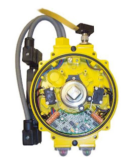
AS Interface
Kinetrol AS Interface
Devices conforming to the AS interface (Actuator Sensor interface) set of open specifications are used to make up control systems based on a two-wire communication cable known as a bus. Up to 31 actuators and sensors (“slaves”) can be connected to the AS interface bus, and can be controlled or monitored by means of a digital signal sent via the bus to and from a “master” device (which can be a computer or a PLC).

The slave devices will always function in response to commands sent by the master device, either to actuate, or to return a message reporting the value of a sensed variable, or both. The AS interface 2.1 specification allows 31 slave devices to be powered by a DC voltage fed into the same two-cable wire used as the communication bus, with allowed power consumption adequate to drive the slave plus a standard pneumatic solenoid valve. Under extended addressing, a maximum of 62 slave devices can be connected via one bus, but specified limits on device capacitance make this applicable only to systems with limited numbers of solenoid valves, or with a special scheme to get round the limit (see overleaf).

An AS interface bus can be used as the final field link in a more complex hierarchy of devices making up a large plant-wide control system. Actuators and sensors must often be installed in unprotected environments where conditions can be demanding; the AS interface bus is ideal for using as the link between these field devices and the “indoor” equipment making up the upper part of the control system.

AS interface is well suited to on/off control and monitoring, and is a good choice when a simple economical, reliable and robust solution is required to control and monitor a series of actuators and sensors in a process control or machine application. Kinetrol’s AS interface Universal Limit Switch Box is designed to meet all of these requirements.


The Kinetrol AS interface circuit board is fitted inside a standard actuator-mounted Kinetrol Universal Limit Switch Box (2 or 4 entry), so that the actuator (and up to 30 others like it) can be controlled, monitored and powered directly via a single two-conductor digital communication cable (or bus), using the open AS interface 2.1 standard. All the advantages of the limit switch box (all-metal construction, corrosion resistant, up to IP67 sealing, easy connection, easy setting of limit switch strikers etc - see KF487 literature) combined with the highly specified AS interface circuit to give unique levels of practicality, genuine industrial quality, and use-anywhere adaptability.

See thr full feature set and documentation below.

Why Vane Actuators Outlast and Outperform Rack & Pinion and Scotch Yoke Designs

Kinetrol vane actuators perform
in the toughest applications.
Due to the use of gears, slides, pins, and yokes, rack & pinion and scotch-yoke design actuators are less reliable than Kinetrol vane actuators.

Kinetrol's design is based upon a single moving part, which eliminates additional parts required to convert linear motion to rotary motion. This simple and innovative design provides a highly accurate and extremely reliable actuator for operating valves, drives and dampers, and is perfectly suited for the most demanding process control control applications.


For more information, visit http://www.kinetrolusa.com

Need a Fail-Safe Valve Operator? Use This One.

Kinetrol manual fail safe spring unit
Kinetrol manual fail-safe
spring unit.
If you want to operate a valve manually, but maintain the advantage of the fail-safe spring’s certainty of position when unattended, use this device.

These spring return units are designed to be put on valves to prevent, or limit, the impact of potentially hazardous accidents resulting from uncontrolled flowing fluid and gasses or spillage.

The Kinetrol manual fail-safe spring unit has a ISO/DIN female drive for direct mounting and ATEX category 2 options for use in hazardous areas. Kinetrol also offers a range of fire fail-safe spring assemblies that can be set to operate valves at pre-configured temperatures.

Because they cannot be left in the wrong position, they are commonly referred to as "deadman handles". Theses devices provide reliable torque delivery for valve reseating and come with completely sealed spring housings that meet IP65 levels, totally protecting the internal spring from the environment, making them ideal for outdoor applications.

Kinetrol FDA Approved Coating

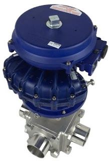
Kinetrol actuator with FDA approved coating
Kinetrol actuator with
FDA approved coating

Products coated with Kinetrol RAL5002 Blueline food grade paint option, have a Kinetrol Variation Product Code: BU. This is suitable for use in the European Union & United States of America for Standard Actuators & Spring Units. For other assemblies including ULS and XLS switchboxes, AP, P3 and EL positioners a special order code will be issued.

For Example: a model 09 ISO Double acting Actuator having this coating would be: 094-100BU or model 09 ANSI Spring Return Actuator clockwise would be 097-120BU.

The product casings are pretreated prior to coating for additional protection. This coating system exhibits the following characteristics:
  1. Good resistance to 'caustic washdown' procedures as typically performed in the food industry. 
  2. It shows exceptional resistance to chipping/flaking. It does not 'chip' in a brittle manner but remains attached to the substrate. 
  3. If in extreme circumstances, the coating becomes dislodged from the product surface, its color is particularly visible to the human eye or sorters/sensors/detectors. 
  4. Good resistance to corrosion in salt laden environments. 5. The coating has good non-stick properties. 
Coating Statement for United States of America:
Kinetrol actuator with FDA approved coating
Kinetrol Blueline coating
now FDA approved.


This coating is permitted for use in contact with food in compliance with the Federal Food, Drug and Cosmetic Act (FDA) and all applicable regulations, including 21 CR 175.300 (Code of Federal Regulations).

Coating Statement for European Union:

When coated in this finish, Kinetrol product casings meet the requirements of German BfR L1 for Temperature Resistant Polymer Coating Systems for Frying, Cooking and Baking Utensils. BfR recognizes that when in contact with food it will not transfer its constituents in quantities that could endanger human health. 

For more information on using Kinetrol actuators in food and pharmaceutical applications contact Kinetrol USA at www.kinetrolusa.com or call 972-447-9443.

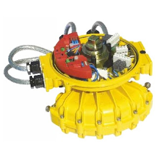
Kinetrol P3 On/Off Positioner

Kinetrol P3 On/Off positioner
Kinetrol P3 On/Off Positioner

The Kinetrol P3 On/Off positioner consists of an electronic positioning circuit mounted in a robust all-metal enclosure, which controls a 1⁄4-turn rotary pneumatic actuator via standard on-off solenoid valves direct-mounted on the actuator’s own interface.

The P3 circuit is designed so that its assembly can be mounted inside a standard Kinetrol limit switch box (either ULS-type, or explosion proof XLS-type), using only two screws. The P3 assembly is complete with feedback potentiometer and anti-backlash gear drive, which engages with gear teeth on the limit switch coupling to read the actuator’s position. The limit switch coupling complete with gear teeth needs to replace the standard coupling if a standard box is being retrofitted with a P3.

The positioner circuit is powered by the mid-point input voltage. It functions by comparing the actual mid-point position (read by the feedback potentiometer) with the set position (set via an on-board preset, or a remote preset, or a remote 4-20mA signal). The positioner circuit uses its solid-state switched outputs to power solenoid valves which drive the actuator towards the position where the set position corresponds with the actual position. When it gets there, the solenoids are switched to hold that position.

Kinetrol P3 On/Off positioner
 Need More Information?
Contact Kinetrol USA at
or call 972-447-9443.

The positioner circuit incorporates a unique power supply allowing it to be powered by any of 24vDC, 48vDC, 115vAC or 230vAC, 50/60 Hz, without the need for any change. The supply maintains full isolation of the low voltage control circuit from the power input line (up to 5Kv). Switching of the solenoid valve outputs is achieved through opto-isolated solid state switches which operate at all the above voltages – only the solenoid coils themselves need to be adapted specifically to the supply voltage. The use of solid state switching avoids any limitations on relay contact life.

Double acting models are available as fail-free (standard), fail-down (moves clockwise on loss of electrical power if air supply is still present) and fail-hold (holds position on loss of electrical and / or air supply) variants. Spring return models move in the direction of the spring on loss of electrical failure, but hold position on loss of air. An external pressure switch (which cuts electrical power on loss of air pressure) should be fitted by the customer if spring function is required on loss of air and / or electrical power.

An optional angle retransmit (AR) circuit can be retrofitted by plugging it into the top of the positioner circuit and fixing with three screws. The AR circuit is a 2-wire loop-powered 4-20mA device, which reads the position of the positioner’s feedback pot. It is fully functional whether or not the positioner circuit is powered, and the feedback signal is electronically isolated (ie. floating) relative to the low voltage positioner circuit (which in turn is electrically isolated from the power supply and solenoid connections).

Extra solid-state switches have been incorporated on the positioner board to allow supply to both solenoid valves via a single cable for movement to the upscale position when the positioner is in spring-return or fail-down mode, while still allowing the positioner to control the two valves independently for the mid position. If the mid-position input is energised, then these extra switches isolate the solenoids from the upscale/downscale inputs.

The three power input lines (for up, mid, down positions) are independently fused using plug-in miniature fuses on the positioner circuit board.

External connections are made via a multi-option connector board, which allows simultaneous connection of up to four changeover limit switches, three control supply inputs plus neutral/negative, and a single low-voltage signal. This connector board, like the positioner circuit assembly, mounts in either the standard ULS or XLS box using two screws.

If an angle retransmit circuit is fitted using the low voltage signal terminal, optional 4-20mA inputs or external setpoint pot wires can be connected either directly to the terminal block on the positioner circuit or, if only three or less limit switches are in use, relayed through an unused limit switch terminal on the connector board.

The limit switch box is fitted with a ground terminal which must be connected to a suitable external ground.

Industrial solenoid valves which permit the use of standard quality air supplies (instrument quality air is not required) are direct-mounted on adaptor blocks on the side of the actuator, and electrically connected via steel-armoured flying leads with DIN sockets on the solenoid end. At the positioner end, they connect to two 2-way terminal blocks on the circuit board. A range of solenoid valve options are available, determined by the function required, the supply voltage, and whether or not the unit requires hazardous area certification. 

KEY FEATURES
  • Robust modulating actuator, control tolerant of standard air quality (instrument air quality is not necessary).
  • Three position rotary control using only three electrical inputs plus air supply.
  • Two endstop positions + adjustable mid position anywhere in angular range of actuator (90 or 180°).
  • Control circuit mounts inside standard all metal industrial quality Kinetrol ULS or XLS limit switch boxes without disturbing limit switches – available fully assembled, or (on non-explosion proof models only) for user retrofit to existing boxes.
  • Direct mounting onto full range of Kinetrol 1⁄4 turn actuators. Namur mounting options available.
  • Uses direct-mounting standard solenoid valves outside box to position actuator.
  • Easy adjustment of mid position set point by switch–selectable choice of methods: on-board pot, remote pot or 4-20mA input signal.
  • Explosion proof options available (approved to IECEX, ATEX; FM (for USA & Canada) standards pending) by use of XLS housing plus standard explosion proof solenoid valves.
  • All new positioner circuit – runs on any of 24vDC, 48vDC, 115vAC or 230vAC power without any change required.
  • Solid-state universal-voltage solenoid switching – no mechanical contacts.
  • Three separate on-board mains fuses for three inputs.
  • Switchable selection of mid-point setting method (on-board preset, remote preset, remote 4-20mA signal).
  • Switchable selection of double acting or spring return operating mode.
  • Power input isolated from signal inputs and outputs for all voltage options.
  • Moulded reinforced plastic internal circuit cover for insulated safety.
  • Positioner has user-adjustable zero, span, deadband and damping parameters via preset pots for easy optimization of positioning performance.
  • Damping parameter gives velocity-proportional setpoint advance to allow better stabilization of fast-moving or high inertia loads while maintaining resolution and repeatability.
  • Retrofittable isolated loop-powered 4-20mA angle-retransmit circuit available – just plugs in inside same enclosure – with its own user-adjustable zero and span presets.
Need More Information?
Contact Kinetrol USA at
www.kinetrolusa.com
or call 972-447-9443.