Control Valve Positioner and Control Valve Actuator Basics

Control Valve Loop
Control Valve Loop*
Control valves control fluid in a pipe by varying the orifice size through which the fluid flows. Control valves contain three major components, the valve body, the positioner, and the valve actuator.

The valve body provides the fluid connections and movable restrictor comprised a valve stem and plug that is in contact with the fluid that varies the flow.

The valve actuator is the component that physically moves the restrictor to vary the fluid flow.

Their are two general categories of control valves - linear and rotary. Three actuator types are used in linear control valves including spring and diaphragm, solenoid, and motor operated. Three actuator types are used in rotary control valves including pneumatic, electric, and electro-hydraulic. Rotary actuators are sometimes referred to as "quarter-turn" or "partial-turn".
Pneumatic positioner on rotary vane actuator
Pneumatic positioner with
rotary vane actuator
on ball valve.

The valve disc (restrictor) controls flow through the valve body. A positioner receives information from a supervisory controller advising wether or not the flow condition is satisfactory. The positioner then provides a signal to the actuator that provides the force to open and close the valve.

Each type of positioner works in response to a process signal. Some positioners (linear) use a 3-15 PSI pneumatic process signal. The pressure is exerted on a large diaphragm creating downward force that is applied against a spring which moves the restrictor up and own. Other types of positioners use a 3-15 PSI pneumatic signal to regulate a higher supply pressure (such as 0-60 PSI) to move pistons or vanes back and forth (rotary). 

The variable 3-15 PSI control signal can be provided directly by a pneumatic controller connected directly to the process, or in other cases the 3-15 PSI is regulated by an electropneumatic device called an I/P or E/P (current to pressure or voltage to pressure) transmitter. These transmitters receive their signal from a supervisory control as a 0-10VDC or 4-20mA and then throttle the 3-15 PSI output to open/close the valve. 

* Image courtesy of Tony R. Kuphaldt from "Lessons In Industrial Instrumentation"

Pneumatic Actuators that Stand Up to Pulp and Paper Plants

Pulp and Paper Process
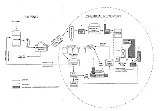
Simplified Pulp and Paper Process Diagram
The "kraft process" (also known as the sulfate process) is the method to convert wood chips into pulp and then to cellulose fibers. This is done by mixing the wood chips with sodium hydroxide and sodium sulphate, soaking, cooking and processing. One reason why the kraft process dominates the paper industry is because of the ability of the kraft chemical recovery process to recover approximately 95 percent of the pulping chemicals and at the same time produce energy in the form of steam.

The purpose of the chemical recovery cycle is to recover cooking liquor chemicals from spent cooking liquor. The process involves concentrating black liquor, combusting organic compounds, reducing inorganic compounds, and reconstituting cooking liquor.

Pulp and Paper Process
Chemical recovery process flow diagram.
Green liquor is created when molten inorganic salts, referred to as "smelt," collect in a char bed at the bottom of the furnace. Smelt is drawn off and  dissolved in weak wash water to form a solution of carbonate salts - known as green liquor - which is primarily Na2S and Na2CO3. Green liquor also contains insoluble unburned carbon and inorganic Impurities, called dregs, which are removed in a series of clarification tanks.

Decanted green liquor is transferred to the causticizing area, where the Na2CO3 is converted to NaOH by the addition of lime (calcium oxide [Ca0]). The green liquor is first transferred to a slaker tank, where Ca0 from the lime kiln reacts with water to form calcium hydroxide (Ca(OH)2). From the slake, liquor flows through a series of agitated tanks, referred to as causticizers, that allow the causticizing reaction to go to completion (i.e., Ca(OH)2 reacts with Na2CO3 to form NaOH and CaCO3).

On the right you see a Kinetrol model 14 double acting actuator on a 8” full-port ball valve on a green liquor line. The valve cycles 2 times per day to direct green liquor flow and weak wash (weak white liquor) alternatively from one pipe to another in order to prevent solids build up in the pipelines.

Equipment used to produce pulp, paper, and paperboard is exposed to a wide range of temperature and humidity conditions, and contaminants. Actuators used in Pulp and Paper manufacturing processes must withstand the most difficult operating conditions.  Kinetrol actuators are preferred in these situations because they don't allow corrosive atmospheres to penetrate the actuator or springs, their long cycle life,  and their epoxy stove enamel finish.

Contact the experts at Kinetrol USA at 972-447-9443 to discuss any pulp and paper mill actuator application.

PROCESS EXPO 2017 is Right Around the Corner!

Get a free pass to the PROCESS EXPO 2017 courtesy of Kinetrol USA!

September 19–22, 2017 • McCormick Place • Chicago, IL USA 

PROCESS EXPO is the nation’s largest trade show dedicated to bringing the latest technology and integrated solutions to all segments of the food and beverage industry.
Kinetrol is featuring the new Blueline Actuator series specifically for the food and beverage industry. Kinetrol Blueline Rotary Vane Actuators provide a superior alternative for actuating quarter-turn valves in food and beverage applications and are guaranteed for up to 4 million operations.

Stop by the Kinetrol booth #2670 and see the difference!

Instructions for your free pass: Visit this link and fill in your information. Or, go to the PROCESS EXPO 2017 site and use code 74768 when registering.

Dampers and Louvers Used in Power Plants, Refineries, Boilers, and Furnaces

parallel damper
Parallel damper with electric actuator.
A damper (otherwise known as a louvre) is a multi-element flow control device generally used to throttle large flows of air at low pressure. Dampers find common application in furnace and boiler draft control, and in HVAC (Heating, Ventilation, and Air Conditioning) systems.

Radial damper
Radial damper.
Common damper designs include parallel and radial. Parallel-vane dampers resemble a Venetian blind, with multiple rectangular vanes synchronously rotated to throttle flow through a rectangular opening. A photograph of a parallel-vane damper is shown above, part of an induced-draft (suction) air fan system on a separator at a cement plant. The vanes are not visible in this photograph because they reside inside the metal air duct, but the electric actuator mechanism and linkages connecting seven vane shafts together are visible.
pneumatic vane actuator damper drive
Pneumatic vane actuator damper drive.

Radial-vane dampers use multiple vanes arranged like petals of a flower to throttle flow through a circular opening. A photograph of a radial-vane damper is shown here (note the levers and linkages on the periphery of the tube, synchronizing the motions of the eight vanes so they rotate at the same angle).

Dampers are opened and closed by electric or pneumatic drives. In recent years, the pneumatic vane actuator  has earned an reputation for modulating dampers. Used in critical applications commonly found in power plants, refineries, boilers, and furnaces, these unique damper drives provide precise combustion gas management, are proven to increase boiler efficiency, lower fuel consumption, reduce emissions, and reduce maintenance cost.


Parts of this post are reprinted from Lessons In Industrial Instrumentation by Tony R. Kuphaldt – under the terms and conditions of the Creative Commons Attribution 4.0 International Public License.

New Blueline Section on Kinetrol USA Website

The Blueline Series actuators and spring return units with food grade coating have been added to the KinetrolUSA.com website.

More information can be found here - http://www.kinetrolusa.com/blueline.

Pneumatic Vane Actuators for Food Processing Applications


Kinetrol USA's "Blueline" Series of pneumatic vane actuators are designed for use in foodservice and beverage processing. The actuators are intended to be installed in areas where harsh chemical wash-down is required. These areas are very tough on most types of pneumatic actuators because the caustic or acidic chemicals used in cleaning adversely effect the actuator. All stainless steel actuators are an alternative, but they are prohibitively expensive. Kinetrol's Blueline Series provides a very economical option.

Blueline Actuators are permitted for use in contact with food in compliance with the Federal Food, Drug and Cosmetic Act (FDA) and all applicable regulations, including 21 CR 175.300 (Code of Federal Regulations).

For more information, call 972-447-9443 or visit http://www.kinetrolusa.com

Integral Vane-Shaft Actuators Best for High Cycle Rate and Modulating Applications

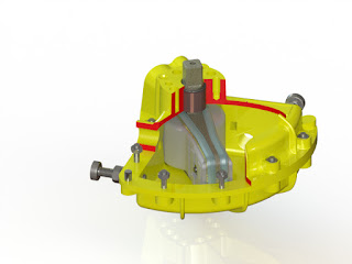
Internal view of vane actuator
Internal view of vane actuator. Note the
single piece vane/shaft design.
Rack and pinion and scotch yoke type pneumatic actuators depend on gears to transfer torque and movement, while integral vane-shaft actuators have no gears (or linkages). As a result,  integral vane-shaft actuators are the hands-down choice for high cycle rate and modulating valve/damper actuation.

Why? Because of the mechanical problems inherent to the use of gears.

According to Wikipedia, "A gear or cogwheel is a rotating machine part having cut teeth, or cogs, which mesh with another toothed part to transmit torque."

The primary disadvantages to gears are:
  • Friction
  • Fretting Wear
  • Backlash
When gears mesh, there is friction. Friction causes heat and wear, which effects the mechanical life of the actuator. Friction converts kinetic energy into thermal energy and can have dramatic consequences if left unchecked. Another important consequence of friction is wear, which may lead to performance degradation and/or damage to the internal components of a rack and pinion or scotch yoke actuator.

"Fretting wear" is caused by the repeated cyclical rubbing between two surfaces (gears in the case of scotch yoke or rack and pinion actuators) and over a period of time, will remove material from one or both surfaces.

Backlash happens when gears change direction. It is caused by the gap between the trailing face of the driving tooth and the leading face of the tooth behind it. The gap must be closed before force can be transferred in the new direction, hence the phenomena of backlash. This is also sometimes referred to as "slop".

For pneumatic actuators with very low cycle rates, or ones that are not used for modulating service, internal gears may be acceptable. However, for applications where there are high cycle rates, or require accurate modulation, the use of a single machined vane actuator with integral shaft is preferred. The reason? No friction, wear, or backlash. 100 percent of the movement of the vane is transferred to the shaft without loss or hysteresis.

For any questions about applying the most appropriate type of actuator for any valve or damper application, call Kinetrol at 972-447-9443 or visit http://www.kinetrolusa.com.