Integral Vane-Shaft Actuators Best for High Cycle Rate and Modulating Applications

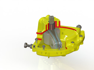
Internal view of vane actuator
Internal view of vane actuator. Note the
single piece vane/shaft design.
Rack and pinion and scotch yoke type pneumatic actuators depend on gears to transfer torque and movement, while integral vane-shaft actuators have no gears (or linkages). As a result,  integral vane-shaft actuators are the hands-down choice for high cycle rate and modulating valve/damper actuation.

Why? Because of the mechanical problems inherent to the use of gears.

According to Wikipedia, "A gear or cogwheel is a rotating machine part having cut teeth, or cogs, which mesh with another toothed part to transmit torque."

The primary disadvantages to gears are:
  • Friction
  • Fretting Wear
  • Backlash
When gears mesh, there is friction. Friction causes heat and wear, which effects the mechanical life of the actuator. Friction converts kinetic energy into thermal energy and can have dramatic consequences if left unchecked. Another important consequence of friction is wear, which may lead to performance degradation and/or damage to the internal components of a rack and pinion or scotch yoke actuator.

"Fretting wear" is caused by the repeated cyclical rubbing between two surfaces (gears in the case of scotch yoke or rack and pinion actuators) and over a period of time, will remove material from one or both surfaces.

Backlash happens when gears change direction. It is caused by the gap between the trailing face of the driving tooth and the leading face of the tooth behind it. The gap must be closed before force can be transferred in the new direction, hence the phenomena of backlash. This is also sometimes referred to as "slop".

For pneumatic actuators with very low cycle rates, or ones that are not used for modulating service, internal gears may be acceptable. However, for applications where there are high cycle rates, or require accurate modulation, the use of a single machined vane actuator with integral shaft is preferred. The reason? No friction, wear, or backlash. 100 percent of the movement of the vane is transferred to the shaft without loss or hysteresis.

For any questions about applying the most appropriate type of actuator for any valve or damper application, call Kinetrol at 972-447-9443 or visit http://www.kinetrolusa.com.

Shark-Tested Rotary Vane Actuators

For those of you who live under a rock, Shark Week  is a week long TV programming block put on by the Discovery Channel. Usually occurring in mid-late July or early August, it features entirely shark-related programming. Everything from great educational documentaries to completely ridiculous events such as Micheal Phelps racing a Great White.

So what does a blog about rotary vane actuators have to do with Shark Week? The answer lies with the good people at MythBusters.

Out to prove (or disprove) the long-standing theory that punching a shark in the nose will scare it away, host Jamie Hyneman had to design a robotic shark punching machine that would deliver a powerful punch, similar to one that a real human being would deliver.

As they have in a past MythBuster episode, the MythBusters team turned to Kinetrol for the crucial piece of equipment - the Kinetrol pneumatic rotary vane actuator.

The result was an underwater "Rock 'em Sock 'em Robot" machine with two arms, each powered by a Kinetrol Model 07 Actuator.


How Kinetrol Pneumatic Rotary Vane Actuators Work

Kinetrol pneumatic rotary vane actuators use a one piece vane and shaft produce rotary torque on the shaft output drive. The vane is assembled inside a 2-piece clam-shell enclosure. The presence of the vane creates two air chambers. By pressurizing and venting opposing chambers, the resulting pressure differential across the vane provides torque to the shaft. Torque output of the rotary vane actuator remains constant throughout the full rotation of the shaft.

Industrial Dampers and Drives

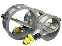
Round dampers with pneumatic vane type drives
Round dampers with
pneumatic vane type drives.

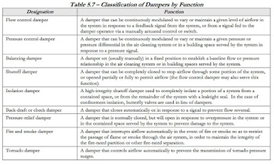
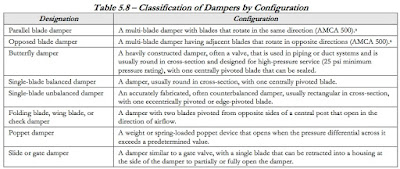
By definition, a damper is a device used to control pressure, flow, or flow direction in an air or gas system. Different types of dampers can be used, depending on specific functional requirements. Table 5.7 below lists the types of dampers and their functions, and Table 5.8 lists the damper configurations. Selection of the proper damper type and blade configuration is important to achieve the required damper performance. The type and configuration of damper can significantly impact pressure drop, leakage rates, and controllability.
dampers by function
Click table for larger view.

dampers by type
Click table for larger view.

pneumatic vane damper drive
Pneumatic vane damper drive.
A very important part of damper design is determination of damper torque and sizing and selection of damper actuator for the maximum torque. Actuator torque should be selected for a minimum of 1.5 times the damper maximum torque to provide margin and allow for degradation over the life of the damper. Actuators should be evaluated for damper blade movement in both directions, at the beginning of blade movement, and while stroking blades through the full cycle of movement.

Damper operators can be one of three types: pneumatic, electric, or electro-hydraulic, as described below.
  1. Pneumatic. These damper operators are used whenever controls rely primarily on compressed air (pneumatic) for moving operators or transmitting control signals.
  2. Electric. These damper operators are used whenever controls rely primarily on low voltage electric circuits to transmit control signals.
  3. Electrohydraulic. These damper operators are the same as the electric type described above, except they have the ability to modulate. They use an electric control signal to position a hydraulic system that, in turn, positions the damper.
Electrically operated damper drives have historically been favored, but the shift to retro-fit electric drives with pneumatic damper drives has been significant in the last two decades. When pneumatic vane actuators were first introduced for damper drive service, their virtues were quickly discovered. Their inherent design and operating advantages apply perfectly for precise damper control. These design and operating advantages are:
  • Damper drives on round dampers.
  • Precise, smooth signal to movement response.
  • 100 percent duty cycle.
  • Continuous modulating service.
  • No overheating.
  • High speed/high-torque.
  • Fast full stroke open/close.
  • Very easily serviced.
  • Excels in harsh, high-temperature operating environments.
  • Effectively zero air consumption in resting state.
For more information on any damper drive application, contact Kinetrol USA at 972-447-9443 or visit http://www.kinetrolusa.com.