A Basic Description of Valve Actuators

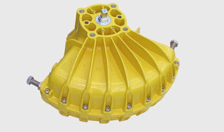
Kinetrol automated plug valve
Automated plug valve with
actuator, limit switch, and indicator.
Valves are used to control the flow of fluids in process systems. In order to meet the needs of a process system some method of changing the positions of the valve is needed. 

Some valves can be operated with hand wheels or levers, but some valves have to be open and closed or throttled frequently. Manually positioning valves in these types of situations is not always practical. So instead of hand wheels or levers, actuators are used to position the valves. 

An actuator is a mechanism that moves or controls a device such as a valve. Actuators reduce the need for operators to go to every valve that needs repositioning and operate the valve by hand. When actuators are used, valves can be repositioned from a central remote location, such as a control room. This is very important in processes where a number of valves have to be repositioned accurately and quickly.

There are three basic types of actuators pneumatic actuators, hydraulic actuators, and electric actuators. Pneumatic actuators use air pressure to produce motion to position the valve. They're probably the most common type of actuator used in process systems. Actuators that are powered by a pressurized liquid, such as hydraulic fluid, are called hydraulic actuators. Compared to pneumatic actuators, hydraulic actuators of the same size are usually more powerful. Electric actuators use electricity to produce motion. They usually fall into one of two general classifications: solenoid actuators or motor-driven actuators. 

Regardless of the type of actuator used with valves, actuators are normally part of process control systems. From a control room, valves with actuators can be quickly and accurately positioned to deal with frequent flow changes. 

Valve actuators operate to position valves in response to signals from controllers. Controllers are part of the instrumentation systems that monitor plant processes and response to variations in the processes. Basically a controller is a device that receives an input from another part of the instrumentation system, compares that input to a set point, and sends out a corrective signal to regulate the value of a process variable such as temperature, pressure, level, or flow. 

Generally, actuators are used with valves that are designed for throttling or regulating flow. Valves that are used to automatically throttle flow are generally referred to as control valves. However some on-off or isolation valves may also require actuators. Although these isolation valves may require actuators, they're not commonly referred to as control valves. Control valves can be either linear that is the stem moves the valve disc up and down as in globe and gate valves, or they can be rotary which means that they're positioned by rotation. Butterfly valves and ball valves, which open or closed with a 90-degree turn, are examples of rotary control valves.
Kinetrol Spring Return Units: Spiral Torsion Springs Are Key

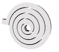
Spiral torsion spring
Simple view of spiral
torsion spring (protruding
tab and hex center
are loading points.)
Spiral torsion springs are found in many places - clocks, watches, timers ... and Kinetrol spring return units!

Capable of storing much more energy than a typical compression spring, and working in smaller, more compact packages, spiral torsion springs for valve and damper actuation are a proven step-up over helical compression springs.

When a torque is applied to a spiral torsion spring, an angular displacement is created between the first and second loading points, the coil deflects (tightens), and the spring material is placed under stress, exerting a linear (to the degree of rotation) rotational "output" torque,  which drives the spring's rotation. Practically speaking, spiral torsion springs allow for lower torque loss, lower torque stress, and much greater reliability for use in valve and damper actuation.

Kinetrol Spring Return
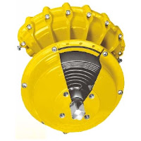
Kinetrol Spring Return Unit
(note cutaway revealing
spiral torsion spring.)
Along with the inherent advantages of spiral torsion springs, additional benefits of the Kinetrol spring return unit are:

  • Separate housing for modular assembly, easily retrofitted
  • Sealed, non-breathing housing: Protects spring in corrosive environments
  • Adjustable pretension for 'balanced' air and spring stroke torques: Various combinations available for balanced / optimized torques at various air pressures
  • Keeper plates available to ensure safe handling of pretensioned springs
  • Available with ISO/DIN female drive and mounting
The combination of the spiral torsion spring reliability plus the advanced engineering design allow Kinetrol to offer a guarantee against failure of the spring unit for the lifetime of the mating actuator!

For more information, contact Kinetrol USA by visiting www.kinetrolusa.com or calling 972-447-9443.


Review: Vane Actuators

vane actuator
An internal view of a vane actuator allowing you
to see the one piece vane and shaft, lip seals,
travel stops, and the clam shell  design.
The vane actuator is a simple and elegant mechanism for quarter-turn valves, dampers, and other rotary motion applications. The vane actuator produces rotary motion through the application of air pressure to a "vane' attached directly to an output shaft. In higher quality vane actuators, the vane and shaft are machined from a single piece of steel. Because of this, any motion from the vane is transferred directly to the shaft, without backlash or lost motion.

The vane includes “lip seals” that isolate the vane and shaft from the air supply. The lip seal design provides several advantages, namely eliminating the need for shaft seals and an inherent cleaning action internally. A split, or “clam-shell” housing is assembled around the vane, totally enclosing it. When supply air is applied to one side of the vane, torque is produced moving the vane in one direction. Accordingly, there is direct rotary motion transfer to the shaft, with 100% efficiency. Torque is controlled by surface area of the vane and the differential pressure on either side of the vane. Bi-directional over-travel is limited by the use of travel stops mounted in both sides of the housing.

The Kinetrol Vane Actuator
Single acting vane actuators use a spring to return the actuator to its resting position. By adding a spring, vane actuators can fail-open or fail-closed in the event of power failure. Double acting actuators use supply air on either side of the actuator to dictate clockwise or counter-clockwise movement. Other types of pneumatic actuators generally require high quality air as their power source, but vane actuators can accept poorer quality supply air, as the vane design uses the vane’s “wiping action” to push dirt and grime out of the way. Vane actuators are generally more compact that other types of actuators and come in many sizes, producing a wide range of torques.

For more information about vane actuators visit http://www.kinetrolusa.com or call 972-447-9443.

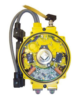
Actuator Sensor Interface for Kinetrol Vane Actuators

AS Interface
Kinetrol AS Interface
Devices conforming to the AS interface (Actuator Sensor interface) set of open specifications are used to make up control systems based on a two-wire communication cable known as a bus. Up to 31 actuators and sensors (“slaves”) can be connected to the AS interface bus, and can be controlled or monitored by means of a digital signal sent via the bus to and from a “master” device (which can be a computer or a PLC).

The slave devices will always function in response to commands sent by the master device, either to actuate, or to return a message reporting the value of a sensed variable, or both. The AS interface 2.1 specification allows 31 slave devices to be powered by a DC voltage fed into the same two-cable wire used as the communication bus, with allowed power consumption adequate to drive the slave plus a standard pneumatic solenoid valve. Under extended addressing, a maximum of 62 slave devices can be connected via one bus, but specified limits on device capacitance make this applicable only to systems with limited numbers of solenoid valves, or with a special scheme to get round the limit (see overleaf).

An AS interface bus can be used as the final field link in a more complex hierarchy of devices making up a large plant-wide control system. Actuators and sensors must often be installed in unprotected environments where conditions can be demanding; the AS interface bus is ideal for using as the link between these field devices and the “indoor” equipment making up the upper part of the control system.

AS interface is well suited to on/off control and monitoring, and is a good choice when a simple economical, reliable and robust solution is required to control and monitor a series of actuators and sensors in a process control or machine application. Kinetrol’s AS interface Universal Limit Switch Box is designed to meet all of these requirements.


The Kinetrol AS interface circuit board is fitted inside a standard actuator-mounted Kinetrol Universal Limit Switch Box (2 or 4 entry), so that the actuator (and up to 30 others like it) can be controlled, monitored and powered directly via a single two-conductor digital communication cable (or bus), using the open AS interface 2.1 standard. All the advantages of the limit switch box (all-metal construction, corrosion resistant, up to IP67 sealing, easy connection, easy setting of limit switch strikers etc - see KF487 literature) combined with the highly specified AS interface circuit to give unique levels of practicality, genuine industrial quality, and use-anywhere adaptability.

See thr full feature set and documentation below.