Showing posts with label valve positioner. Show all posts

Proportional Spool Valve + Robust Force Balance Mechanism = Smooth and Accurate Control

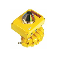
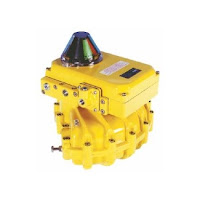
Kinetrol's AP pneumatic positioner
Kinetrol's AP pneumatic positioner.
Kinetrol's AP pneumatic positioner combines the smoothness and accuracy of Kinetrol’s proven mechanical positioner technology (using a proportional spool valve driven by a simple, accurate and robust force balance mechanism) with new advances in convenience and simplicity of use, derived from the unique innovative design both of the internal mechanism and of the overall package.

The result is a positioner with unparalleled performance and real industrial robustness, easy to calibrate and characterize, and adaptable to the whole range of applications with a great list of options:
  • High flow valves
  • Direct mount or industry standard discrete mount housings
  • 4-20mA angle retransmit
  • Limit switches
  • Clear Cone position monitor
  • I/P convertors (either simple or with various explosion proof options)
Kinetrol's AP pneumatic positionerOPERATING PRINCIPLES

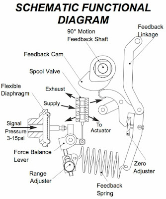
The AP positioner is designed to drive a rotary or linear actuator to a position set by a 3-15 psi (0.2-1.0 bar) signal and hold it there until the signal changes.

When a signal pressure is applied to the diaphragm it moves the force balance lever clockwise against the tension of the feedback spring. This moves the spool valve, supplying air pressure to one side of the actuator while exhausting trapped air from the other side. The feedback shaft follows the movement of the actuator and turns the cam counter clockwise, pushing the cam follower and increasing the tension on the feedback spring until it balances the force on the diaphragm and moves the spool valve to its central ‘hold’ position.

The relationship between the input signal and desired position (the ‘characteristic’) is determined by the cam profile. A linear 3-15 psi (0.2 - 1.0 bar) signal / 0-90° output movement cam is standard. Split range, fast opening, equal percentage or customized characteristic cams are available.

See the brochure below for detailed information and illustrations. For more information, contact Kinetrol USA at http://www.kinetrolusa.com or call 972-447-9443.

Accuracy, Smooth Operation, and Efficiency Key to Industrial Valve Postioner

EL electro-pneumatic positioner
The EL electro-pneumatic positioner combines the precision and adaptability of a digital electronic control circuit with the smoothness and efficiency of Kinetrol's proven proportional servo valve, to give the best available 4-20mA positioning performance from rotary pneumatic actuators. This unbeatable performance is combined with the easiest available setup procedure, easiest access to all functions and options, easy connectibility, and a truly compact all-metal enclosure, plus unique easy-set isolated angle retransmit and limit switch options inside the same enclosure.

The EL positioner is designed to drive a rotary or linear actuator to a position set by the 4-20 mA input signal, and then hold it there until the signal changes.

The microprocessor in the loop powered 4-20 mA positioner circuit reads signal via one channel of a 12-bit A-D convertor, reads the position voltage from tie pot via the second channel of the A-D convertor, and compares the two. If it detects a position different from that required by the signal, it changes its output to the servo valve in order to drive the actuator in the direction required to reach the correct position. As the actuator moves, the feedback pot voltage changes, and the microprocessor continually calculates how to adjust the servo valve in order to guide the actuator accurately into position. Because the servo valve is a fully proportional device, it can be adjusted precisely and smoothly to slow the actuator to a stop exactly where it should be.  The microprocessor is programmed with a sophisticated but compact algorithm which allows this critical dynamic valve adjustment to be made correctly to give optimal results with any actuator/load combination - slow or fast, low friction or high friction, low inertia or high inertia, all can be optimized by PGAIN and DAMP parameters via the positioner circuit pushbuttons. The 12-bit A-D conversion gives resolution of about 1/40 degree.

EL positioner curve
EL positioner curve
The relationship between the input signal and desired position (the "characteristic") is stored in the microprocessor's memory. It can be set to follow any one of eleven pre-programmed curves between its two endpoints. The endpoints (each a combination of a signal value and a position) are set by the user via the pushbuttons. One of the eleven curves is a linearly proportional characteristic - this characteristic only can be selected to give movement of the actuator for signals extrapolated below the low endpoint and above the high endpoint, or to stop dead on signals below the low and above tie high endpoint. The "stop dead" behavior is the only option for the other ten non-linear curves.

The settings entered by the user are stored in non - volatile memory, and are retained even if power (i.e. signal) is lost.

Kinetrol EL Positioner Option: Special Characteristic for Butterfly Valve Linear Flow Control

EL Positioner
EL Positioner

EL positioner option: Special characteristic to give butterfly valve control for linear valve flow vs. input signal.

Upon request Kinetrol can supply a positioner fitted with a circuit that will provide an output characteristic to suit a butterfly valve. By replacing the standard circuit (with 10 non-linear and one linear control response curves) by one containing a microprocessor programmed with 10 different non-linear curves and one linear, the valve can be controlled to give optimum flow control with a butterfly valve.

In general the pressure drop across a valve will change as the valve opens, and this changes the flow/valve position characteristic. The five solid line curves on the graph linearise the response for valve pressure drops which fall to a range of values as the valve is opened fully, see below.

The values below are the pressure drop with the valve full open expressed as a percentage of the pressure drop with the valve closed.
  • Curve -1 for 100% (this should be used to linearize a butterfly valve which is operating with a constant pressure drop)
  • Curve -2 for 30%
  • Curve -3 for 10%
  • Curve -4 for 3% 
  • Curve -5 for 1%
Click on graph for larger view.
Example 

A butterfly valve controlling the flow of a fluid with a 10% constant pressure drop, gives 50% of its fully open flow at an angle of opening of roughly 40 degrees. We would thus recommend the user set the control response to curve -3, here 12mA (half signal) would open the valve to 40 degrees to allow 50% flow rate. The user can select one of the eleven pre-programmed curves by going into SETUP mode.