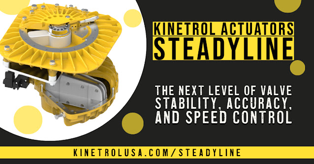
The Kinetrol Steadyline series are precision valve actuators with built-in damping devices that give smooth rotational resistance to the actuator/valve shaft. Water hammer occurs when a pipe's fluid flow changes rapidly. The effect may be high pipe pressures, mechanical stress on pipe structures, and potential flow reversal. If not controlled, it can cause pipe bursting, pipe breaking, and joint leakage. The Kinetrol Steadyline actuators smooth the actuator's standard travel. It dampens any pipeline flow-induced oscillations of the valve disks and enables the user to set a minimum amount of travel time on power failure. As a result, the Kinetrol Steadyline provides better performance, reduced downtime, and lower operating costs.
For more information visit Kinetrolusa.com/steadyline or call 972-447-9443.The Kinetrol rotary vane design is based upon a single moving part which eliminates additional parts required to convert linear motion to rotary motion. This simple and innovative design provides a highly accurate and extremely reliable actuator for operating valves, drives and dampers, and is perfectly suited for the most demanding process control applications. For more information visit www.kinetrolusa.com or call 972-447-9443.
Showing posts with label control valve. Show all posts
Showing posts with label control valve. Show all posts
Power Plant Bearing Cooling Water Temperature Control
A midwest power plant was using a diaphragm control valve to control water temperature for their bearing cooling system. The closed-loop bearing cooling system uses the modulating valve to control water temperature between 50 and 170 degrees F. at 170 PSIG. The diaphragm valve was not able to provide the required signal response for tight control.
The local Kinetrol Distributor specified a high performance butterfly valve (HPBV) with Kinetrol spring return actuator and third-party positioner. The new valve and actuator package provided reliable and accurate controllability with zero hysteresis. It has operated continually for 3 years without maintenance.
The local Kinetrol Distributor specified a high performance butterfly valve (HPBV) with Kinetrol spring return actuator and third-party positioner. The new valve and actuator package provided reliable and accurate controllability with zero hysteresis. It has operated continually for 3 years without maintenance.
 |
| Bearing Cooling Water Temperature Control Valve |
Pneumatic Actuators Well-suited for Offshore Valve and Damper Applications
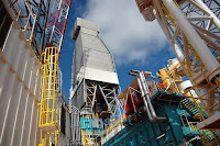 |
| Offshore Platform |
Corrosion
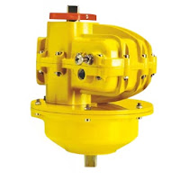 |
| Corrosion resistant housing and sealed spring. |
Vibration
Constant structural vibration, caused by the dynamic forces generated by compressors, pumps, and engines, leads to poor equipment reliability and eventual failure. Pulsating and shaking forces expedite wear on mechanical connections such as gears and yoke mechanisms, with many gear failures due to resonant vibration.
Space
Oil platform actuators, control valves, safety valves, and piping systems are configured very similarly to their terra firma cousins, with the major difference between land and platform equipment being reduced weight and size. Space is at a premium and it is critical to keep equipment as compact as possible.
 |
| Single moving part. No gears or yokes. |
Kinetrol rotary vane actuators provide an excellent solution, well-suited for off-shore and marine applications. A durable epoxy stove enamel finish and corrosion resistant zinc (non-incendive) or aluminum alloy case protect the actuator from the harsh environment.
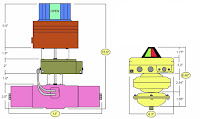 |
| Size comparison for similar output. |
Finally, Kinetrol vance actuators only require 1/3 to 1/2 the required installation space of similarly equipped rack and pion actuators.
For more information, contact Kinetrol USA by visiting https://www.kinetrolusa.com or calling 972-447-9443.
Control Valve Positioner and Control Valve Actuator Basics
 |
| Control Valve Loop* |
Control valves control fluid in a pipe by varying the orifice size through which the fluid flows. Control valves contain three major components, the valve body, the positioner, and the valve actuator.
The valve body provides the fluid connections and movable restrictor comprised a valve stem and plug that is in contact with the fluid that varies the flow.
The valve body provides the fluid connections and movable restrictor comprised a valve stem and plug that is in contact with the fluid that varies the flow.
The valve actuator is the component that physically moves the restrictor to vary the fluid flow.
Their are two general categories of control valves - linear and rotary. Three actuator types are used in linear control valves including spring and diaphragm, solenoid, and motor operated. Three actuator types are used in rotary control valves including pneumatic, electric, and electro-hydraulic. Rotary actuators are sometimes referred to as "quarter-turn" or "partial-turn".
The valve disc (restrictor) controls flow through the valve body. A positioner receives information from a supervisory controller advising wether or not the flow condition is satisfactory. The positioner then provides a signal to the actuator that provides the force to open and close the valve.
Each type of positioner works in response to a process signal. Some positioners (linear) use a 3-15 PSI pneumatic process signal. The pressure is exerted on a large diaphragm creating downward force that is applied against a spring which moves the restrictor up and own. Other types of positioners use a 3-15 PSI pneumatic signal to regulate a higher supply pressure (such as 0-60 PSI) to move pistons or vanes back and forth (rotary).
The variable 3-15 PSI control signal can be provided directly by a pneumatic controller connected directly to the process, or in other cases the 3-15 PSI is regulated by an electropneumatic device called an I/P or E/P (current to pressure or voltage to pressure) transmitter. These transmitters receive their signal from a supervisory control as a 0-10VDC or 4-20mA and then throttle the 3-15 PSI output to open/close the valve.
* Image courtesy of Tony R. Kuphaldt from "Lessons In Industrial Instrumentation"
Proportional Spool Valve + Robust Force Balance Mechanism = Smooth and Accurate Control
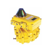 |
| Kinetrol's AP pneumatic positioner. |
The result is a positioner with unparalleled performance and real industrial robustness, easy to calibrate and characterize, and adaptable to the whole range of applications with a great list of options:
- High flow valves
- Direct mount or industry standard discrete mount housings
- 4-20mA angle retransmit
- Limit switches
- Clear Cone position monitor
- I/P convertors (either simple or with various explosion proof options)
 OPERATING PRINCIPLES
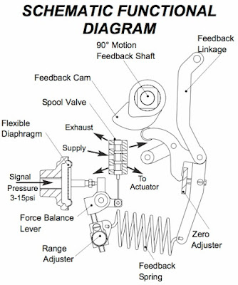
The AP positioner is designed to drive a rotary or linear actuator to a position set by a 3-15 psi (0.2-1.0 bar) signal and hold it there until the signal changes.
When a signal pressure is applied to the diaphragm it moves the force balance lever clockwise against the tension of the feedback spring. This moves the spool valve, supplying air pressure to one side of the actuator while exhausting trapped air from the other side. The feedback shaft follows the movement of the actuator and turns the cam counter clockwise, pushing the cam follower and increasing the tension on the feedback spring until it balances the force on the diaphragm and moves the spool valve to its central ‘hold’ position.
The relationship between the input signal and desired position (the ‘characteristic’) is determined by the cam profile. A linear 3-15 psi (0.2 - 1.0 bar) signal / 0-90° output movement cam is standard. Split range, fast opening, equal percentage or customized characteristic cams are available.
See the brochure below for detailed information and illustrations. For more information, contact Kinetrol USA at http://www.kinetrolusa.com or call 972-447-9443.
Accuracy, Smooth Operation, and Efficiency Key to Industrial Valve Postioner
 |
| EL electro-pneumatic positioner |
The EL positioner is designed to drive a rotary or linear actuator to a position set by the 4-20 mA input signal, and then hold it there until the signal changes.
The microprocessor in the loop powered 4-20 mA positioner circuit reads signal via one channel of a 12-bit A-D convertor, reads the position voltage from tie pot via the second channel of the A-D convertor, and compares the two. If it detects a position different from that required by the signal, it changes its output to the servo valve in order to drive the actuator in the direction required to reach the correct position. As the actuator moves, the feedback pot voltage changes, and the microprocessor continually calculates how to adjust the servo valve in order to guide the actuator accurately into position. Because the servo valve is a fully proportional device, it can be adjusted precisely and smoothly to slow the actuator to a stop exactly where it should be. The microprocessor is programmed with a sophisticated but compact algorithm which allows this critical dynamic valve adjustment to be made correctly to give optimal results with any actuator/load combination - slow or fast, low friction or high friction, low inertia or high inertia, all can be optimized by PGAIN and DAMP parameters via the positioner circuit pushbuttons. The 12-bit A-D conversion gives resolution of about 1/40 degree.
 |
| EL positioner curve |
The settings entered by the user are stored in non - volatile memory, and are retained even if power (i.e. signal) is lost.
Water Recycling Application at Iron Ore Mine
 Mining corporations need water - a lot of water - to make bare rock give up its valuable minerals.
Water is used for the extraction of minerals that may be in the form of solids, such as coal, iron, sand, and gravel. The category includes quarrying, and milling (crushing, screening, washing, and flotation of mined materials).
Not only is water used to expose the mineral, it must be carefully managed to prevent the release of contaminated water back into the environment.
There are multiple processes involving the management of water that require piping, valves and automation for water management.
- The reuse of water used to extract the minerals from the other solids.
- Managing surface water from rain, snow, and streams.
- Capturing and recycling water from the mine site.
- Storing water in evaporation ponds.
The Distributor designed and provided this characterized butterfly control valve, with a Kinetrol actuator, pneumatic positioner, and cone indicator. The valve is used to recycle processed water back into the plant for reuse in the extraction process. The valve and actuator experiences a very high cycle rate (400 cycles per day).
Intercepting and diverting surface water
- Intercepting and diverting surface water (rain and snowmelt runoff, streams, and creeks) from entering the mine site by building upstream dams to reduce the potential for water contamination from exposed ore and waste rock
- Recycling water used for processing ore in order to reduce the volume of water requiring treatment
- Capturing drainage water from precipitation at the mine site through the use of liners and pipes and directing the water to tailings dams in order to prevent potentially contaminated water from entering groundwater or flowing off site
- Allowing the water to evaporate in ponds to reduce the volume of contaminated water; in dry regions, enough water may be evaporated that no water needs to be discharged, resulting in the containment of contaminates at the mine site
- Installing liners and covers on waste rock and ore piles to reduce the potential for contact with precipitation and contamination of groundwater
Segment Ball Control Valve with Vane Actuator, Pneumatic Positioner, and I/P Transmitter
 |
| Actuator and Positioner |
In most cases standard ball, plug, or butterfly valves are not the best choice as control valves (where the process media has to be modulated or throttled). Standard ball, plug and butterfly valves usually introduce very non-linear, dynamic flow coefficients. Furthermore, they can introduce undesirable turbulence to your piping system.
As a means to linearize flow coefficients and reduce turbulent flow, the machining, or characterization, of the valve disk is done so that the machined shape allows for more optimized flow.
For ball valves in particular, machining the ball's flow port with a "V", or even by machining the ball more radically, can deliver excellent flow curves. A term for a more radically machined ball is the "segment ball" (sometimes called "segmented"). In the following video you can see how a Kinetrol pneumatic actuator, postioner, and I/P transmitter team up with a segment ball valve foe an excellent control valve.
Labels:
actuation,
automation,
ball,
butterfly,
control valve,
Kinetrol,
plug,
segment,
V port,
valve
A Cheesy Application for a Kinetrol Actuator & Positioner
 |
| Kinetrol Actuator, Positioner and Spring on Steam Line in Cheese Making Plant |
Its a tough application, and critical to keep running. Losing steam supply is very costly because of production losses and access to the valve is difficult.
The plant maintenance people tried a few of the more well-known valve/actuator packages without success. These packages would last a few weeks (a couple months at best), before failing. Frustrated and out of answers, the maintenance crew turned to a local Kinetrol Distributor salesperson for advice.
Knowing Kinetrol actuators, spring units and positioners are designed for the toughest applications, the salesperson specified the 097-120 on top of a Triad v-ported ball valve. Hopeful, but with little optimism, the maintenance crew installed the 1-1/2 control valve on the steam line and fired the system up.
For 11 months now (without any downtime), 24 hours a day, this lonely control valve, powered by a Kinetrol positioner and vane actuator, accurately throttles the steam supply and reliably keeps the cheese process line running.
Problem solved by Kinetrol!
EL Electropneumatic Positioner
The EL positioner controls airflow to an actuator and moves it to a position determined by a 4-20mA signal and using a unique low power proportional servo valve.
The microprocessor in the loop-powered 4- 20mA position circuit reads the signal via one channel of a 12-bit A-D converter, reads the position voltage from the feedback potentiometer via the second channel of the
A-D converter, and compares the two. If it detects a position which is different from that required by the signal, it changes the output to the servo valve, in order to drive the actuator in the direction required to reach the correct position. As the actuator moves, the feedback potentiometer voltage changes and the microprocessor continually calculates the adjustments required for the servo valve in order to guide the actuator accurately into position. The microprocessor is programmed with a sophisticated but compact algorithm which allows this critical dynamic valve adjustment to be made correctly. This in turn gives optimal results with any actuator/load combination - slow or fast, low or high friction, low or high inertia. All can be optimized by tuning the PGAIN and DAMP push buttons via the positioner circuit push buttons.
Subscribe to:
Comments (Atom)
