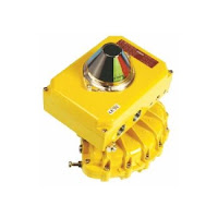
Kinetrol EL Positioner Option: Special Characteristic for Butterfly Valve Linear Flow Control

EL Positioner
EL Positioner

EL positioner option: Special characteristic to give butterfly valve control for linear valve flow vs. input signal.

Upon request Kinetrol can supply a positioner fitted with a circuit that will provide an output characteristic to suit a butterfly valve. By replacing the standard circuit (with 10 non-linear and one linear control response curves) by one containing a microprocessor programmed with 10 different non-linear curves and one linear, the valve can be controlled to give optimum flow control with a butterfly valve.

In general the pressure drop across a valve will change as the valve opens, and this changes the flow/valve position characteristic. The five solid line curves on the graph linearise the response for valve pressure drops which fall to a range of values as the valve is opened fully, see below.

The values below are the pressure drop with the valve full open expressed as a percentage of the pressure drop with the valve closed.
  • Curve -1 for 100% (this should be used to linearize a butterfly valve which is operating with a constant pressure drop)
  • Curve -2 for 30%
  • Curve -3 for 10%
  • Curve -4 for 3% 
  • Curve -5 for 1%
Click on graph for larger view.
Example 

A butterfly valve controlling the flow of a fluid with a 10% constant pressure drop, gives 50% of its fully open flow at an angle of opening of roughly 40 degrees. We would thus recommend the user set the control response to curve -3, here 12mA (half signal) would open the valve to 40 degrees to allow 50% flow rate. The user can select one of the eleven pre-programmed curves by going into SETUP mode.

Kinetrol + Plug Valve = Optimum Sludge Valve Performance

water treatment valves
Water treatment plant
Sewage sludge is the semi-solid material that is produced during sewage treatment of industrial or municipal wastewater. Sludge blowdown valves are used in water and wastewater treatment systems that separate solids prior to filtration. These valves are particularly susceptible to fouling and ultimately prone to failure.

Many valve manufacturers specify high-pressure/high-torque actuators to overcome the sludge. Many times they choose linear type valves and screw-type linear actuators because they provide the brute force needed to push through the sludge. An unwanted side-effect of using linear valves and actuators is that the same force used to push the disc through the sludge, also causes valve damage by pushing and grinding solids into the valve seats, disc and seals. Eventually, the valve becomes so damaged it no longer provides proper shut-off.

Kinetrol actuator
Kinetrol actuator
Pneumatic scotch yoke and rack and pinion actuators, with quarter-turn valves, can provide the torque required for opening and closing the valve, and the nature of some quarter-turn valve designs protect internal parts from damage. Plug valves are designed this way and when combined with double acting pneumatic actuators that operate on a controlled time frequency, are a very reliable design for this application. The cycle frequency depends on the amount of solids in the media, and cycle times of opening and closing every 20 minutes are common. This cycle rate however, is problematic for scotch yoke and rack and pinion actuators, causing them to fail prematurely. In some cases the actuators fail in only 3 - 4 months of use.

For sludge applications, Kinetrol rotary vane actuators mounted on quarter-turn plug valves are a great choice . The combination of the high cycle actuator design, with the design benefits of a plug valve, offer wastewater treatment operators a valve assembly that will provide years of trouble-free life.

Kinetrol Series 180 - 189 Actuator Spring Removal Replacement Instructions

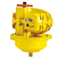
Kinetrol Spring Return Actuator
Kinetrol Spring
Return Actuator
Spring removal/replacement instructions for 180/189 spring return actuators.

For more information, visit www.kinetrolusa.com or call 972-447-9443.

Fit and Forget, Worry-free Pneumatic Valve Actuators

Here's a short, narrated introduction to the Kinetrol vane actuator and their use on industrial valves. Kinetrol's 60 years of applying "fit & forget, worry about something else" actuators has rightfully earned their reputation for being the most durable, long-lasting valve actuator on the market today - a statement backed by a 4 million cycle warranty and documented, real-world field installations where the actuator provided upwards of 30 million maintenance-free cycles.


For more information, visit http://www.kinetrolusa.com.

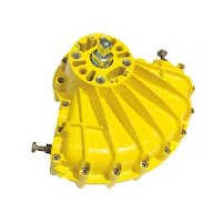
What Is a Vane Actuator?

Vane Actuator
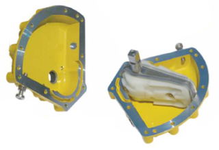
Inside view of a vane actuator showing the clam-shell
design, internal chamber layout, and double-sided vane.
Vane actuators use pneumatic or hydraulic power to open, close, or modulate quarter-turn valves, dampers, louvers, as well as for precise movement of ergonomic lifting equipment.

Linear motion gas/hydraulic cylinder or piston actuators use gears to convert linear to rotary motion. Vane actuators employ a rigid vane inside a sealed chamber that is connected directly to the drive shaft at one end with no gears. The result is much smoother rotary movement and greater cycle life.

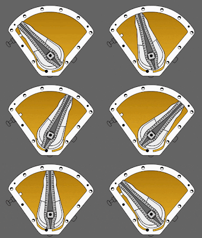
Vane actuators operate by introducing a fluid or gas to either side of it's enclosure through inlet/outlet ports, creating the force required for movement. Advanced vane actuators utilize double sided vanes that allow for pressurization of both sides, allowing for bi-directional movement. The vane itself provides an arc movement in the far side (opposite the shaft) of the actuator, translating rotary movement back to its integrated shaft.

The vane actuator shaft is designed to connect directly to a device (valve, damper, ergo mechanism) for the transfer of movement. In advanced design vane actuators, the shaft is completely sealed from the pressurized side of the vane via “lip seals” which act to prevent the loss of air/gas/oil through shaft seals or bearings. With the help of spring steel supports, the lip seals are kept in constant contact with the inner surface of the chamber wall at all times during rotation. A side benefit of lip seals are the self-cleaning or sweeping action they provide to the inside chamber surfaces.

Since the double-sealed vane separates the vane actuator chamber in two sides, movement in either direction can be changed merely by creating a pressure differential on either side of the vane. Inlet/outlet ports allow for the pressurization and de-pressurization for either side. As gas or fluid is introduced to one side, the vane is forced away, toward the opposite side. By reversing the pressure and vent ports, and pressurizing the opposite chamber, the actuator moves in the opposite direction.

When vane actuators use only gas or fluid as their source for movement in both directions, they are referred to as “double acting”. When an optional spring is used to provide the power in one direction (open or close) they are referred to as “spring return”.

For more information on vane actuators, visit http://www.kinetrolusa.com

Kinetrol Clear Cone Monitor & Solenoid Valve Cut Sheet

The optional Clear Cone provides all round high visibility position monitoring on all limit switch boxes and positioner models. A red/green colour coded monitor is sealed inside a robust, clear polycarbonate cover. Positioner models are marked with black printed legible angle scales.

As an option Kinetrol actuator sizes 03 to 15 can be supplied with integral solenoid valves with NAMUR interface. Air is ported through the actuator body via an adaptor so no external tubing is necessary

See the full cut sheet below:

Vane Actuators Perform Better: Its All About the Gears (or Lack Thereof)

Why do vane actuators consistently outlast rack and pinion and scotch yoke actuators? The truth is in the gears.

Gears wear.

Surface wear, contact fatigue, scuffing and tooth bending are all real-life issues when dealing with gears. Surface wear affects gear contact in such a way that accelerates failure modes by increasing contact stresses and load distributions. This always leads to reduced accuracy and loss of smooth operation. Wear can never be completely eliminated, and over time, progresses at a more rapid rate.

rack and pinion
Typical rack and pinion design - note gear arrangement
Types of Stress on a Gear
  • Sliding stress - causes surface fatigue damage.
  • Rolling stress - causes contact fatigue damage.
  • Bending stress - like a cantilever beam, always deforms. 


rotary vane actuator
Vane actuator - no gears


Pure simplicity - the rotary vane.

One moving part. No gears.

The rotary vane actuator design is based upon a single moving part which eliminates gears required to convert linear motion to rotary motion. This simple and innovative concept provides an extremely reliable mechanism for operating valves, drives and dampers.

More Accurate Control

Another advantage rotary vane actuators have over rack & pinion and scotch yoke actuators is in smoothness and accuracy of control. The more mechanical connections the actuator has, the greater the cumulative hysteresis, and the lower the control responsiveness and accuracy.

For long, trouble-free performance, choose a rotary vane actuator for your next valve actuation or damper drive requirement. You'll be very glad in the long run.