Valve Failure Modes

failsafe spring
Failsafe spring lever on ball valve.
(Kinetrol)
An important design parameter of a control valve is the position it will “fail” to if it loses motive power. For electrically actuated valves, this is typically the last position the valve was in before loss of electric power. For pneumatic and hydraulic actuated valves, the option exists of having a large spring provide a known “fail-safe” position (either open or closed) in the event of fluid pressure (pneumatic air pressure or hydraulic oil pressure) loss.

Available Failure Modes

Valve fail mode may be shown in instrument diagrams by either an arrow pointing in the direction of failure (assuming a direct-acting valve body where stem motion toward the body closes and stem motion away from the body opens the valve trim) and/or the abbreviations “FC” (fail closed) and “FO” (fail open). Other failure modes are possible, as indicated by this set of valve symbols:


In order for a pneumatic or hydraulic valve to fail in the locked state, an external device must trap fluid pressure in the actuator’s diaphragm or piston chamber in the event of supply pressure loss.
Valves that fail in place and drift in a particular direction are usually actuated by double-acting pneumatic piston actuators. These actuators do not use a spring to provide a deļ¬nite fail mode, but rather use air pressure both to open and to close the valve. In the event of an air pressure loss, the actuator will neither be able to open nor close the valve, and so it will tend to remain in position. If the valve is of the globe design with unbalanced trim, forces exerted on the valve plug will move it in one direction (causing drift).


Reprinted from "Lessons In Industrial Instrumentation" by Tony R. Kuphaldt – under the terms and conditions of the Creative Commons Attribution 4.0 International Public License.

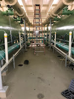
Upper Midwest Water Treatment Plant says "Out with the old, in with the new!"

water treatment valves
Before project.
water treatment valves
Project begins.
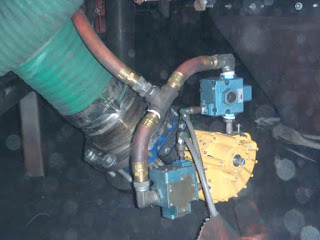
An Upper Midwest water treatment plant was experiencing high failure rates, long maintenance periods, and too many repair issues with their existing pneumatic scotch-yoke cylinder valve operators. 

Upon investigation, the problem boiled down to how the scotch-yoke cylinder's linear movement is converted to rotational movement. To do so requires gearing, yokes and linkage which are wear points. In medium to high cycle rate applications these wear points soon become failure points

Kinetrol rotary vane actuators utilize a single moving part - the one-piece vane and shaft.  There are no gears, yokes, or linkages and 100% of the movement is transferred to the actuator shaft. The one piece vane and shaft eliminates these wear points, and therefore eliminates the resulting failure points.

water treatment valves
Out with the old.
water treatment valves
In with the new.
After a planning review meeting, this particular water treatment plant clearly saw the advantages of the Kinetrol design. The argument was so strong and the case so clear,  they decided to replace all (60) scotch-yoke cylinder actuated valves with Kinetrol vane actuators in one fell swoop. 

The new actuators have been operating for 6 months now without problem, cycling approximately 15 times per day. 

Click on the images above to see a larger view. For more information, contact Kinetrol USA by visiting https://kinetrolusa.com or by calling 972-447-9443

The Kinetrol Actuator Vane Assembly Design

The Kinetrol rotary vane actuator utilizes an advanced design vane assembly that is engineered to provide millions of trouble-free cycles. This video highlights the advanced features that make it the most reliable 1/4 turn pneumatic actuator on the market today.


Kinetrol Actuators Stand Up to Tough Iron Foundry Environment and Very High Cycle Rate

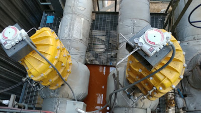
high cycle exhaust valve
Kinetrol on high cycle valve.
A iron foundry located in the Midwest asked the local Kinetrol distributor to help him replace a failing rack and pinion actuator on a on a very high cycle exhaust valve. The environment was very hot and dirty and the actuator cycles approximately 100,000 times per month, which is about 1.3 million per year. Also, the valve has to open in a fraction of a second.

The rack and pinion actuator was replaced with a Kinetrol vane actuator and the customer's problem disappeared. The Kinetrol actuators have performed for over 2 years now without problem.

Click on any of the pictures for a larger view.

high cycle exhaust valve

high cycle exhaust valve


Kinetrol Actuator "Insures" Rapid Valve Closing to Protect Equipment, Infrastructure, and Personnel

20" high performance butterfly valve with Kinetrol actuator
20" high performance
butterfly valve with
Kinetrol actuator
An insurance mandate required a major chemical company who produces PTA (Purified Terephthalic Acid) to install a 20" automatic high performance butterfly valve with the capability to stroke from fully opened to fully closed in less than one second.

Requirement:
It's necessary to prevent a $30M USD axial process air compressor from rapidly going into an overspeed condition that could harm equipment, infrastructure, and personnel. 

Challenge:
20" high performance butterfly valve with Kinetrol actuatorThe biggest challenges: stroking the valve in under one second, but without slamming the butterfly disc into the stops which can damage the valve and nearby equipment. 

Solution:
Kinetrol's expertise in rapid cycling enabled us to size, select, and perform certified cycle time tests on the final assembly. This shut out any competition. 

Assembly: 
20" class 300 high performance butterfly valve, Kinetrol 207-120 with a 2" automatic L-Port, 3-way, compressed air supply ball valve with 097-F120, X-proof solenoid, and two exhaust silencers coupled to the size 20 supply port. Open / closed limit switch assembly. Robust SST mounting bracket and coupling. The closure time once actuator air is exhausted: 0.13 seconds.


Kinetrol Blueline Actuator for Use in Foodservice and Beverage Processing

Kinetrol's "Blueline" Series of pneumatic vane actuators for use in foodservice and beverage processing. The actuators are intended to be installed in areas where harsh chemical wash-down is required. These areas are very tough on most types of pneumatic actuators because the caustic or acidic chemicals used in cleaning adversely effect the actuator. Kinetrol's Blueline Series provides a very economical option these areas.

972-447-9443


Challenging Steam Balancing Valve Application at Southwest Power Plant

Steam Balance Valve
Steam balance valve
with Kinetrol model 30.
In combined-cycle power generation plants, the most common design for managing high-pressure steam is with cascading bypass systems. Balancing valves are used on the hot reheat line to respond to control loop demands. The application is difficult because of high pressures, high temperatures, and large valve sizes (high torque). The valves must shut off tightly and also be capable of precise throttling.

Outfitting these valves with pneumatic actuators is also difficult. Because of the valve size and valve design, actuators must have high torque output, without taking up vast amounts of space. The actuators must also act quickly and eliminate hysteresis.

Most pneumatic actuator designs simply cannot meet the operating and size restrictions, and hydraulic actuators, with all of their associated maintenance problems, are used instead.

A Kinetrol Distributor in the Southwest USA was asked to recommend a better alternative to a line where very large scotch-yoke actuators controlling two (2) 18" valves were controlling poorly and were taking up too much space.

The Distributor's challenge was to:
  • Deliver very high torque output.
  • Provide as small a package as possible.
  • Improve the actuators stability and reliability.
The solution was to apply Kinetrol model 30 vane actuators. The model 30's deliver 168,000 lbf (at 100 psi) of torque in a compact envelope (comparatively). Additionally, the Kinetrol Model 30's, combined with third-party digital valve positioners, provided the precision and response the application required to eliminate oscillations and instability.  The actuators cycle about 20 times per day and have been performing without problem for years. Huge annual fuel savings can be directly attributed to the actuators reliability and precision due to fewer turbine restarts.

Steam Balance Valve
Power plant steam balancing valves in service.

For more information, contact Kinetrol USA by visiting https://kinetrolusa.com or by calling 972-447-9443.