Why Do Kinetrol Actuators Last So Long?


Kinetrol actuators are known world-wide for their extremely long service life, even in harsh environments. Here are a few reasons why.

KintrolUSA.com
972-447-9443

Kinetrol Actuators Protect People and Property with Reliable Performance in Chemical Plant Fire

Kinetrol actuator in safety application
The Kinetrol actuator is completely
unrecognizable,  having been melted in a fire.
A chemical plant in the Southeast USA that manufactures PTA (purified terephthalic acid) experienced a compressor house fire, causing extensive equipment damage and shutting down production for months.

The building houses a $30 million dollar compressor that supplies process air to reactors to begin the PTA manufacturing process.

As part of the safety system, (2) two 6" class 150 high performance butterfly valves with Kinetrol 097-120 and open/closed limit switches were installed on process air lines of one production unit.

During the fire, the two Kinetrol actuated valve assemblies performed exactly as required, shutting the valves tightly and keeping them shut even after the heat of the fire completely melted the actuator housings.

Kinetrol actuator
Closer view.
The actuators had been in service one year at the time of the fire.  Unlike many other Kinetrol actuator applications, these were not chosen for their high cycle capability,  nor for their long service life. In this application Kinetrol was chosen for their absolute reliability in critical situations.

For more information, contact Kinetrol USA by calling 972-447-9443 or by visiting https://kinetrolusa.com.

Valve Failure Modes

failsafe spring
Failsafe spring lever on ball valve.
(Kinetrol)
An important design parameter of a control valve is the position it will “fail” to if it loses motive power. For electrically actuated valves, this is typically the last position the valve was in before loss of electric power. For pneumatic and hydraulic actuated valves, the option exists of having a large spring provide a known “fail-safe” position (either open or closed) in the event of fluid pressure (pneumatic air pressure or hydraulic oil pressure) loss.

Available Failure Modes

Valve fail mode may be shown in instrument diagrams by either an arrow pointing in the direction of failure (assuming a direct-acting valve body where stem motion toward the body closes and stem motion away from the body opens the valve trim) and/or the abbreviations “FC” (fail closed) and “FO” (fail open). Other failure modes are possible, as indicated by this set of valve symbols:


In order for a pneumatic or hydraulic valve to fail in the locked state, an external device must trap fluid pressure in the actuator’s diaphragm or piston chamber in the event of supply pressure loss.
Valves that fail in place and drift in a particular direction are usually actuated by double-acting pneumatic piston actuators. These actuators do not use a spring to provide a deļ¬nite fail mode, but rather use air pressure both to open and to close the valve. In the event of an air pressure loss, the actuator will neither be able to open nor close the valve, and so it will tend to remain in position. If the valve is of the globe design with unbalanced trim, forces exerted on the valve plug will move it in one direction (causing drift).


Reprinted from "Lessons In Industrial Instrumentation" by Tony R. Kuphaldt – under the terms and conditions of the Creative Commons Attribution 4.0 International Public License.

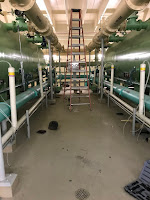
Upper Midwest Water Treatment Plant says "Out with the old, in with the new!"

water treatment valves
Before project.
water treatment valves
Project begins.
An Upper Midwest water treatment plant was experiencing high failure rates, long maintenance periods, and too many repair issues with their existing pneumatic scotch-yoke cylinder valve operators. 

Upon investigation, the problem boiled down to how the scotch-yoke cylinder's linear movement is converted to rotational movement. To do so requires gearing, yokes and linkage which are wear points. In medium to high cycle rate applications these wear points soon become failure points

Kinetrol rotary vane actuators utilize a single moving part - the one-piece vane and shaft.  There are no gears, yokes, or linkages and 100% of the movement is transferred to the actuator shaft. The one piece vane and shaft eliminates these wear points, and therefore eliminates the resulting failure points.

water treatment valves
Out with the old.
water treatment valves
In with the new.
After a planning review meeting, this particular water treatment plant clearly saw the advantages of the Kinetrol design. The argument was so strong and the case so clear,  they decided to replace all (60) scotch-yoke cylinder actuated valves with Kinetrol vane actuators in one fell swoop. 

The new actuators have been operating for 6 months now without problem, cycling approximately 15 times per day. 

Click on the images above to see a larger view. For more information, contact Kinetrol USA by visiting https://kinetrolusa.com or by calling 972-447-9443

The Kinetrol Actuator Vane Assembly Design

The Kinetrol rotary vane actuator utilizes an advanced design vane assembly that is engineered to provide millions of trouble-free cycles. This video highlights the advanced features that make it the most reliable 1/4 turn pneumatic actuator on the market today.


Kinetrol Actuators Stand Up to Tough Iron Foundry Environment and Very High Cycle Rate

high cycle exhaust valve
Kinetrol on high cycle valve.
A iron foundry located in the Midwest asked the local Kinetrol distributor to help him replace a failing rack and pinion actuator on a on a very high cycle exhaust valve. The environment was very hot and dirty and the actuator cycles approximately 100,000 times per month, which is about 1.3 million per year. Also, the valve has to open in a fraction of a second.

The rack and pinion actuator was replaced with a Kinetrol vane actuator and the customer's problem disappeared. The Kinetrol actuators have performed for over 2 years now without problem.

Click on any of the pictures for a larger view.

high cycle exhaust valve

high cycle exhaust valve