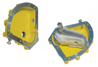
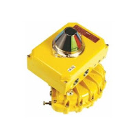
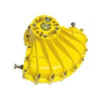
Kinetrol FDA Approved Coating

Kinetrol actuator with FDA approved coating
Kinetrol actuator with
FDA approved coating

Products coated with Kinetrol RAL5002 Blueline food grade paint option, have a Kinetrol Variation Product Code: BU. This is suitable for use in the European Union & United States of America for Standard Actuators & Spring Units. For other assemblies including ULS and XLS switchboxes, AP, P3 and EL positioners a special order code will be issued.

For Example: a model 09 ISO Double acting Actuator having this coating would be: 094-100BU or model 09 ANSI Spring Return Actuator clockwise would be 097-120BU.

The product casings are pretreated prior to coating for additional protection. This coating system exhibits the following characteristics:
  1. Good resistance to 'caustic washdown' procedures as typically performed in the food industry. 
  2. It shows exceptional resistance to chipping/flaking. It does not 'chip' in a brittle manner but remains attached to the substrate. 
  3. If in extreme circumstances, the coating becomes dislodged from the product surface, its color is particularly visible to the human eye or sorters/sensors/detectors. 
  4. Good resistance to corrosion in salt laden environments. 5. The coating has good non-stick properties. 
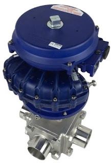
Coating Statement for United States of America:
Kinetrol actuator with FDA approved coating
Kinetrol Blueline coating
now FDA approved.


This coating is permitted for use in contact with food in compliance with the Federal Food, Drug and Cosmetic Act (FDA) and all applicable regulations, including 21 CR 175.300 (Code of Federal Regulations).

Coating Statement for European Union:

When coated in this finish, Kinetrol product casings meet the requirements of German BfR L1 for Temperature Resistant Polymer Coating Systems for Frying, Cooking and Baking Utensils. BfR recognizes that when in contact with food it will not transfer its constituents in quantities that could endanger human health. 

For more information on using Kinetrol actuators in food and pharmaceutical applications contact Kinetrol USA at www.kinetrolusa.com or call 972-447-9443.
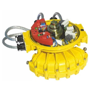
Kinetrol P3 On/Off Positioner

Kinetrol P3 On/Off positioner
Kinetrol P3 On/Off Positioner

The Kinetrol P3 On/Off positioner consists of an electronic positioning circuit mounted in a robust all-metal enclosure, which controls a 1⁄4-turn rotary pneumatic actuator via standard on-off solenoid valves direct-mounted on the actuator’s own interface.

The P3 circuit is designed so that its assembly can be mounted inside a standard Kinetrol limit switch box (either ULS-type, or explosion proof XLS-type), using only two screws. The P3 assembly is complete with feedback potentiometer and anti-backlash gear drive, which engages with gear teeth on the limit switch coupling to read the actuator’s position. The limit switch coupling complete with gear teeth needs to replace the standard coupling if a standard box is being retrofitted with a P3.

The positioner circuit is powered by the mid-point input voltage. It functions by comparing the actual mid-point position (read by the feedback potentiometer) with the set position (set via an on-board preset, or a remote preset, or a remote 4-20mA signal). The positioner circuit uses its solid-state switched outputs to power solenoid valves which drive the actuator towards the position where the set position corresponds with the actual position. When it gets there, the solenoids are switched to hold that position.

Kinetrol P3 On/Off positioner
 Need More Information?
Contact Kinetrol USA at
or call 972-447-9443.

The positioner circuit incorporates a unique power supply allowing it to be powered by any of 24vDC, 48vDC, 115vAC or 230vAC, 50/60 Hz, without the need for any change. The supply maintains full isolation of the low voltage control circuit from the power input line (up to 5Kv). Switching of the solenoid valve outputs is achieved through opto-isolated solid state switches which operate at all the above voltages – only the solenoid coils themselves need to be adapted specifically to the supply voltage. The use of solid state switching avoids any limitations on relay contact life.

Double acting models are available as fail-free (standard), fail-down (moves clockwise on loss of electrical power if air supply is still present) and fail-hold (holds position on loss of electrical and / or air supply) variants. Spring return models move in the direction of the spring on loss of electrical failure, but hold position on loss of air. An external pressure switch (which cuts electrical power on loss of air pressure) should be fitted by the customer if spring function is required on loss of air and / or electrical power.

An optional angle retransmit (AR) circuit can be retrofitted by plugging it into the top of the positioner circuit and fixing with three screws. The AR circuit is a 2-wire loop-powered 4-20mA device, which reads the position of the positioner’s feedback pot. It is fully functional whether or not the positioner circuit is powered, and the feedback signal is electronically isolated (ie. floating) relative to the low voltage positioner circuit (which in turn is electrically isolated from the power supply and solenoid connections).

Extra solid-state switches have been incorporated on the positioner board to allow supply to both solenoid valves via a single cable for movement to the upscale position when the positioner is in spring-return or fail-down mode, while still allowing the positioner to control the two valves independently for the mid position. If the mid-position input is energised, then these extra switches isolate the solenoids from the upscale/downscale inputs.

The three power input lines (for up, mid, down positions) are independently fused using plug-in miniature fuses on the positioner circuit board.

External connections are made via a multi-option connector board, which allows simultaneous connection of up to four changeover limit switches, three control supply inputs plus neutral/negative, and a single low-voltage signal. This connector board, like the positioner circuit assembly, mounts in either the standard ULS or XLS box using two screws.

If an angle retransmit circuit is fitted using the low voltage signal terminal, optional 4-20mA inputs or external setpoint pot wires can be connected either directly to the terminal block on the positioner circuit or, if only three or less limit switches are in use, relayed through an unused limit switch terminal on the connector board.

The limit switch box is fitted with a ground terminal which must be connected to a suitable external ground.

Industrial solenoid valves which permit the use of standard quality air supplies (instrument quality air is not required) are direct-mounted on adaptor blocks on the side of the actuator, and electrically connected via steel-armoured flying leads with DIN sockets on the solenoid end. At the positioner end, they connect to two 2-way terminal blocks on the circuit board. A range of solenoid valve options are available, determined by the function required, the supply voltage, and whether or not the unit requires hazardous area certification. 

KEY FEATURES
  • Robust modulating actuator, control tolerant of standard air quality (instrument air quality is not necessary).
  • Three position rotary control using only three electrical inputs plus air supply.
  • Two endstop positions + adjustable mid position anywhere in angular range of actuator (90 or 180°).
  • Control circuit mounts inside standard all metal industrial quality Kinetrol ULS or XLS limit switch boxes without disturbing limit switches – available fully assembled, or (on non-explosion proof models only) for user retrofit to existing boxes.
  • Direct mounting onto full range of Kinetrol 1⁄4 turn actuators. Namur mounting options available.
  • Uses direct-mounting standard solenoid valves outside box to position actuator.
  • Easy adjustment of mid position set point by switch–selectable choice of methods: on-board pot, remote pot or 4-20mA input signal.
  • Explosion proof options available (approved to IECEX, ATEX; FM (for USA & Canada) standards pending) by use of XLS housing plus standard explosion proof solenoid valves.
  • All new positioner circuit – runs on any of 24vDC, 48vDC, 115vAC or 230vAC power without any change required.
  • Solid-state universal-voltage solenoid switching – no mechanical contacts.
  • Three separate on-board mains fuses for three inputs.
  • Switchable selection of mid-point setting method (on-board preset, remote preset, remote 4-20mA signal).
  • Switchable selection of double acting or spring return operating mode.
  • Power input isolated from signal inputs and outputs for all voltage options.
  • Moulded reinforced plastic internal circuit cover for insulated safety.
  • Positioner has user-adjustable zero, span, deadband and damping parameters via preset pots for easy optimization of positioning performance.
  • Damping parameter gives velocity-proportional setpoint advance to allow better stabilization of fast-moving or high inertia loads while maintaining resolution and repeatability.
  • Retrofittable isolated loop-powered 4-20mA angle-retransmit circuit available – just plugs in inside same enclosure – with its own user-adjustable zero and span presets.
Need More Information?
Contact Kinetrol USA at
www.kinetrolusa.com
or call 972-447-9443.

Valve Actuators for Bottom Ash High Pressure Spray Removal

coal burning power plant
Coal burning power plant
The pulverized coal boiler is the most common type of coal-burning furnace in the electric utility industry. After the pulverized coal is burned in a dry, bottom boiler, approximately 80 % of the unburned material or ash gets captured and recovered as fly ash. The remaining 20% of ash is categorized as bottom ash, a dark gray, granular, porous ash that is collected in a water-filled hopper at the bottom of the furnace. When a sufficient amount of bottom ash is collected in the hopper, it is purged by high pressure water jets into sluiceways or other conveyances for further processing.

Kinetrol Actuator
Kinetrol Rotary Vane Actuator
The high pressure water (approx. 400 PSI) is actually recycled ash water and is very abrasive. The valves and control systems used to move the bottom ash slurry are typically 3” to 12” double offset, high-performance butterfly valves. Double acting pneumatic actuators are most common for opening and closing. Cycle frequency varies, but most typically are between 3 to 12 times per day.

Its crucial that the double offset valves seat completely and are truly “zero-leakage”. In this high pressure and high abrasion scenario, even the slightest leak will cause a rapid failure of the valve seat.

Rack and pinion, scotch yoke, and electric actuators are problematic because of the inherent hysteresis in their gearing. This hysteresis compounds over time adding to the amount of error introduced and increasing the likelihood of a poorly closed valve.

Rotary vane actuators, on the other hand, provide “hysteresis-free” seating due to their single moving part and one piece vane and shaft design. When mounted to the butterfly valves with a no-play coupler, the valve disc is guaranteed to close tightly, without degradation over time.

Additional benefits of using the vane actuator is smooth, controlled closing to reduce the possibility of water hammer and the greater ability work in poor quality atmospheres, both of which are considerations for this application.

Cement Silos Need Valve Actuators with Power and Reliability

Kinetrol on cement silo valve
Kinetrol spring return actuator on cement silo valve.
A silo is a structure for storing bulk materials. The cement silo is an integral piece of equipment for any concrete production operation as it allows the product to be stored, purchased and distributed in bulk. Fitted beneath silos, various types of butterfly or other rotary valves are used to control the flow of cement into trucks or other transport devices.

One particular cement processing plant needed a replacement for their main silo off loading valves. These valves fill cement trucks the company used to deliver their product.

The plant's existing valves were poorly applied for this use and were causing major headaches. The valves were designed with thin steel plate, large gaps between the valve body and disc, and rubber seals that wore away, leading to cement leaking through the valve. The leaking cement would spill onto a feed trough where it would cake and require manual cleaning - an expensive and time consuming operation. If the valve didn’t leak, this expense and time would be saved.

A custom valve manufacturer was called in to use their engineering and fabrication expertise to develop a custom valve that would last. The result was a new rotary valve that uses a much hardier wear plate, and the rotor and body are carefully machined with only a 2/100ths of an inch gap between them. Additionally, the design provides a mechanism to catch any cement should any ever make it through the gap.

The new, custom designed valve needed an actuator that would be equally reliable. The selection of Kinetrol vane actuator with a spring return was the most obvious because its power and its reliability. With only one moving part and no complex linkage to wear out, it was the best choice for long life. The combination of valve and actuator is expected to last many thousands of operations with no maintenance.

Procedure for Calculating Distance of Actuator from Hot Valve

The purpose of this post is to assist in determining the proper distance of a Kinetrol actuator from a hot valve.

In many situation, valves are put inline with a hot process media flowing through the piping system. In these situations, careful consideration must be taken to avoid over temperature exposure of the Kinetrol actuator via conductive or radiant heat.

The following formulae will assist in giving you data to calculate the safe distance between hot valve and actuator.


For steel RHS mount kits, standard (80°C Max.) actuators In ambient 50°C air. 


If you need assistance, or have any concerns about properly distancing the actuator from your process, it's always best to consult with the experts at Kinetrol USA. They're just a phone call away.
For more information visit www.kinetrolusa.com or call 972-447-9443.

Kinetrol EL Positioner Option: Special Characteristic for Butterfly Valve Linear Flow Control

EL Positioner
EL Positioner

EL positioner option: Special characteristic to give butterfly valve control for linear valve flow vs. input signal.

Upon request Kinetrol can supply a positioner fitted with a circuit that will provide an output characteristic to suit a butterfly valve. By replacing the standard circuit (with 10 non-linear and one linear control response curves) by one containing a microprocessor programmed with 10 different non-linear curves and one linear, the valve can be controlled to give optimum flow control with a butterfly valve.

In general the pressure drop across a valve will change as the valve opens, and this changes the flow/valve position characteristic. The five solid line curves on the graph linearise the response for valve pressure drops which fall to a range of values as the valve is opened fully, see below.

The values below are the pressure drop with the valve full open expressed as a percentage of the pressure drop with the valve closed.
  • Curve -1 for 100% (this should be used to linearize a butterfly valve which is operating with a constant pressure drop)
  • Curve -2 for 30%
  • Curve -3 for 10%
  • Curve -4 for 3% 
  • Curve -5 for 1%
Click on graph for larger view.
Example 

A butterfly valve controlling the flow of a fluid with a 10% constant pressure drop, gives 50% of its fully open flow at an angle of opening of roughly 40 degrees. We would thus recommend the user set the control response to curve -3, here 12mA (half signal) would open the valve to 40 degrees to allow 50% flow rate. The user can select one of the eleven pre-programmed curves by going into SETUP mode.

Kinetrol + Plug Valve = Optimum Sludge Valve Performance

water treatment valves
Water treatment plant
Sewage sludge is the semi-solid material that is produced during sewage treatment of industrial or municipal wastewater. Sludge blowdown valves are used in water and wastewater treatment systems that separate solids prior to filtration. These valves are particularly susceptible to fouling and ultimately prone to failure.

Many valve manufacturers specify high-pressure/high-torque actuators to overcome the sludge. Many times they choose linear type valves and screw-type linear actuators because they provide the brute force needed to push through the sludge. An unwanted side-effect of using linear valves and actuators is that the same force used to push the disc through the sludge, also causes valve damage by pushing and grinding solids into the valve seats, disc and seals. Eventually, the valve becomes so damaged it no longer provides proper shut-off.

Kinetrol actuator
Kinetrol actuator
Pneumatic scotch yoke and rack and pinion actuators, with quarter-turn valves, can provide the torque required for opening and closing the valve, and the nature of some quarter-turn valve designs protect internal parts from damage. Plug valves are designed this way and when combined with double acting pneumatic actuators that operate on a controlled time frequency, are a very reliable design for this application. The cycle frequency depends on the amount of solids in the media, and cycle times of opening and closing every 20 minutes are common. This cycle rate however, is problematic for scotch yoke and rack and pinion actuators, causing them to fail prematurely. In some cases the actuators fail in only 3 - 4 months of use.

For sludge applications, Kinetrol rotary vane actuators mounted on quarter-turn plug valves are a great choice . The combination of the high cycle actuator design, with the design benefits of a plug valve, offer wastewater treatment operators a valve assembly that will provide years of trouble-free life.