Proportional Spool Valve + Robust Force Balance Mechanism = Smooth and Accurate Control

Kinetrol's AP pneumatic positioner
Kinetrol's AP pneumatic positioner.
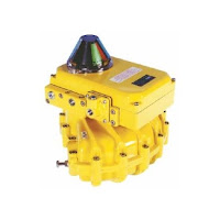
Kinetrol's AP pneumatic positioner combines the smoothness and accuracy of Kinetrol’s proven mechanical positioner technology (using a proportional spool valve driven by a simple, accurate and robust force balance mechanism) with new advances in convenience and simplicity of use, derived from the unique innovative design both of the internal mechanism and of the overall package.

The result is a positioner with unparalleled performance and real industrial robustness, easy to calibrate and characterize, and adaptable to the whole range of applications with a great list of options:
  • High flow valves
  • Direct mount or industry standard discrete mount housings
  • 4-20mA angle retransmit
  • Limit switches
  • Clear Cone position monitor
  • I/P convertors (either simple or with various explosion proof options)
Kinetrol's AP pneumatic positionerOPERATING PRINCIPLES

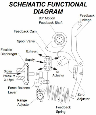
The AP positioner is designed to drive a rotary or linear actuator to a position set by a 3-15 psi (0.2-1.0 bar) signal and hold it there until the signal changes.

When a signal pressure is applied to the diaphragm it moves the force balance lever clockwise against the tension of the feedback spring. This moves the spool valve, supplying air pressure to one side of the actuator while exhausting trapped air from the other side. The feedback shaft follows the movement of the actuator and turns the cam counter clockwise, pushing the cam follower and increasing the tension on the feedback spring until it balances the force on the diaphragm and moves the spool valve to its central ‘hold’ position.

The relationship between the input signal and desired position (the ‘characteristic’) is determined by the cam profile. A linear 3-15 psi (0.2 - 1.0 bar) signal / 0-90° output movement cam is standard. Split range, fast opening, equal percentage or customized characteristic cams are available.

See the brochure below for detailed information and illustrations. For more information, contact Kinetrol USA at http://www.kinetrolusa.com or call 972-447-9443.

Kinetrol Blueline Series Food, Beverage, and Pharma Pneumatic Actuators

Here's a new, short video about the Kinetrol Blueline Series actuator. The Blueline Series of pneumatic vane actuators for use in foodservice and beverage processing. The actuators are intended to be installed in areas where harsh chemical wash-down is required.

Kinetrol Blueline Features:
  • Very good resistance to "caustic wash-down" procedures as typically performed in the food industry.
  • Very good resistance to corrosion In salt laden environments.
  • Meets the FDA’s resinous and polymeric standard. 

Accuracy, Smooth Operation, and Efficiency Key to Industrial Valve Postioner

EL electro-pneumatic positioner
The EL electro-pneumatic positioner combines the precision and adaptability of a digital electronic control circuit with the smoothness and efficiency of Kinetrol's proven proportional servo valve, to give the best available 4-20mA positioning performance from rotary pneumatic actuators. This unbeatable performance is combined with the easiest available setup procedure, easiest access to all functions and options, easy connectibility, and a truly compact all-metal enclosure, plus unique easy-set isolated angle retransmit and limit switch options inside the same enclosure.

The EL positioner is designed to drive a rotary or linear actuator to a position set by the 4-20 mA input signal, and then hold it there until the signal changes.

The microprocessor in the loop powered 4-20 mA positioner circuit reads signal via one channel of a 12-bit A-D convertor, reads the position voltage from tie pot via the second channel of the A-D convertor, and compares the two. If it detects a position different from that required by the signal, it changes its output to the servo valve in order to drive the actuator in the direction required to reach the correct position. As the actuator moves, the feedback pot voltage changes, and the microprocessor continually calculates how to adjust the servo valve in order to guide the actuator accurately into position. Because the servo valve is a fully proportional device, it can be adjusted precisely and smoothly to slow the actuator to a stop exactly where it should be.  The microprocessor is programmed with a sophisticated but compact algorithm which allows this critical dynamic valve adjustment to be made correctly to give optimal results with any actuator/load combination - slow or fast, low friction or high friction, low inertia or high inertia, all can be optimized by PGAIN and DAMP parameters via the positioner circuit pushbuttons. The 12-bit A-D conversion gives resolution of about 1/40 degree.

EL positioner curve
EL positioner curve
The relationship between the input signal and desired position (the "characteristic") is stored in the microprocessor's memory. It can be set to follow any one of eleven pre-programmed curves between its two endpoints. The endpoints (each a combination of a signal value and a position) are set by the user via the pushbuttons. One of the eleven curves is a linearly proportional characteristic - this characteristic only can be selected to give movement of the actuator for signals extrapolated below the low endpoint and above the high endpoint, or to stop dead on signals below the low and above tie high endpoint. The "stop dead" behavior is the only option for the other ten non-linear curves.

The settings entered by the user are stored in non - volatile memory, and are retained even if power (i.e. signal) is lost.

Save The Date! Kinetrol Exhibiting at Valve World Expo 2017

Kinetrol will be exhibiting at Valve World Expo 2017.

Come visit us at BOOTH #335

The Valve World Americas event will cover a variety of valve and valve-related topics that are essential to today’s valve market.

Date:
June 20 and 21st, 2017

Location:
George R. Brown Convention Center
1001 Avenida De Las Americas
Houston, TX 77010
USA

Exhibition Hours
Tuesday, June 20 from 09:00AM until 5:00PM
Wednesday, June 21 from 09:00AM until 5:00PM

Avoid Fretting and Backlash with Rotary Vane Actuators

fretting and backlash shorten actuator life
Fretting and backlash
shorten actuator life and
negatively affects controllability
over time.
The American Society for Metals Handbook on Fatigue and Fracture defines fretting as: "A special wear process that occurs at the contact area between two materials under load and subject to minute relative motion by vibration or some other force."

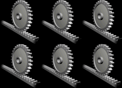
In pneumatic valve actuators, fretting wear is caused by the repeated cyclical rubbing between gears in scotch yoke or rack and pinion actuators. Over a period of time, fretting will remove material from one or both surfaces. This extra material, or debris, is usually harder than its source material due to work hardening and oxidation. The resulting debris becomes an even more effective abrasive, increasing the rate of mechanical wear and continued fretting.

Backlash happens when gears change direction. It is caused by the gap between the trailing face of the driving tooth and the leading face of the tooth behind it. The gap must be closed before force can be transferred in the new direction, hence the phenomena of backlash. This is also sometimes referred to as "slop".

Both fretting and backlash significantly effect the service life of an pneumatic valve or damper actuator. Both are also detrimental to controllability when actuators are used to accurately manage the percent open status of a valve or damper.

rotary vane actuators
Internal view of a rotary vane actuators.
Notice the vane is constructed from
a single piece of stock and
contains no gears.
An alternative actuator design is the rotary vane design that uses a single piece of machined steel for both the vane body and drive shafts. With this design, the shaft and vane are not affected by backlash, friction or wear. Vane actuator's incorporate a design with only a single moving part that provides very repeatable, smooth movement that will not decay over time.

For more information, visit http://www.KinetrolUSA.com or call 972-447-9443.

The Role of Industrial Valve Actuators

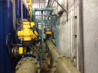
Kinetrol pneumatic actuators installed on pipeline.
Valves are essential to industry. Valve automation refers to
the electric, pneumatic, or hydraulic systems deployed to
open, close or position the valve.
Valves are essential to industries which constitute the backbone of the modern world. The prevalence of valves in engineering, mechanics, and science demands that each individual valve performs to a certain standard. Just as the valve itself is a key component of a larger system, the valve actuator is as important to the valve as the valve is to the industry in which it functions. Actuators are powered mechanisms that position valves between open and closed states; the actuators are controllable either by manual control or as part of an automated control loop, where the actuator responds to a remote control signal. Depending on the valve and actuator combination, valves of different types can be closed, fully open, or somewhere in-between. Current actuation technology allows for remote indication of valve position, as well as other diagnostic and operational information. Regardless of its source of power, be it electric, hydraulic, pneumatic, or another, all actuators produce either linear or rotary motion under the command of a control source.

Thanks to actuators, multiple valves can be controlled in a process system in a coordinated fashion; imagine if, in a large industrial environment, engineers had to physically adjust every valve via a hand wheel or lever! While that manual arrangement may create jobs, it is, unfortunately, completely impractical from a logistical and economic perspective. Actuators enable automation to be applied to valve operation.

Pneumatic vane actuator with spring return and positioner
Pneumatic vane actuator
with spring return and positioner
on plastic body valve.
Pneumatic actuators utilize air pressure as the motive force which changes the position of a valve.
Pressurized-liquid reliant devices are known as hydraulic actuators. Electric actuators, either motor driven or solenoid operated, rely on electric power to drive the valve trim into position. With controllers constantly monitoring a process, evaluating inputs, changes in valve position can be remotely controlled to provide the needed response to maintain the desired process condition.

Manual operation and regulation of valves is becoming less prevalent as automation continues to gain traction throughout every industry. Valve actuators serve as the interface between the control intelligence and the physical movement of the valve. The timeliness and automation advantages of the valve actuators also serve as an immense help in risk mitigation, where, as long as the system is functioning correctly, critical calamities in either environmental conditions or to a facility can be pre-empted and quickly prevented. Generally speaking, manual actuators rely on hand operation of levers, gears, or wheels, but valves which are frequently changed (or which exist in remote areas) benefit from an automatic actuator with an external power source for a myriad of practical reasons, most pressingly being located in an area mostly impractical for manual operation or complicated by hazardous conditions.

Thanks to their versatility and stratified uses, actuators serve as industrial keystones to, arguably, one of the most important control elements of industries around the world. Just as industries are the backbones of societies, valves are key building blocks to industrial processes, with actuators as an invaluable device ensuring both safe and precise operation.