Pneumatic Valve and Damper Actuators Designed to Stand Up to the Cement Industry

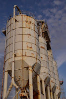
Cement silo
Cement silos.
Cement plants take a harsh toll on equipment such as valves and actuators. Abrasive material is involved from the beginning to the end. Materials handled are often dusty and cause severe abrasive wear of equipment. The movement, blending, storage, and transport of limestone, shale, iron ore, and clay wreaks havoc on the life expectancy of process equipment. Additionally, corrosion issues in cement plants are frequent and costly.

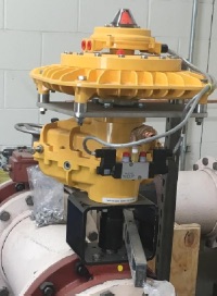
Because of their reliability and ruggedness, Kinetrol rotary vane actuators are used in many processes across a cement plant. These applications include vehicle unloading, silo discharge, air cooling dampers, distribution, bagging and emissions control.

You can download a PDF that outlines where vane actuators are used in all areas of cement production here, or you can read the embedded document below.

Industrial Valve Actuator Types

Lever actuator
Lever actuator
(with failsafe  spring return)
Valve actuators are selected based upon a number of factors including torque necessary to operate the valve and the need for automatic actuation. Types of actuators include manual handwheel, manual lever, electrical motor, pneumatic, and solenoid. All actuators except manual handwheel and lever are adaptable to automatic actuation.

Manual

Manual actuators are capable of placing the valve in any position but do not permit automatic operation. The most common type mechanical actuator is the handwheel. This type includes handwheels fixed to the stem and handwheels connected to the stem through gears.

Electric Motor Actuators
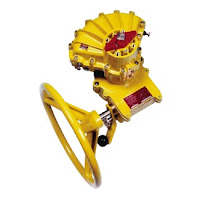
handwheel gear operator
Gear operator
(attached to pneumatic actuator)

Electric motors permit manual, semi-automatic, and automatic operation of the valve. Motors are used mostly for open-close functions, although they are adaptable to positioning the valve to any point opening. The motor is usually a, reversible, high speed type connected through a gear train to reduce the motor speed and thereby increase the torque at the stem. Direction of motor rotation determines direction of disk motion. The electrical actuation can be semi-automatic, as when the motor is started by a control system. A handwheel, which can be engaged to the gear train, provides for manual operating of the valve. Limit switches are normally provided to stop the motor automatically at full open and full closed valve positions. Limit switches are operated either physically by position of the valve or torsionally by torque of the motor.

Pneumatic Actuators
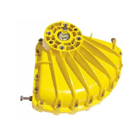
Pneumatic actuator
Pneumatic actuator
Pneumatic actuators provide for automatic or semi-automatic valve operation. These actuators translate an air signal into valve stem motion by air pressure acting on a vane, diaphragm, or piston connected to the stem. Pneumatic actuators are used in throttle valves for open-close positioning where fast action is required. When air pressure closes the valve and spring action opens the valve, the actuator is termed direct-acting. When air pressure opens the valve and spring action closes the valve, the actuator is termed reverse-acting. Double acting actuators have air supplied to both sides of the vane, diaphragm, or piston. The differential pressure across the diaphragm positions the valve stem. Automatic operation is provided when the air signals are automatically  controlled by circuitry. Semi-automatic operation is provided by manual switches in the circuitry to the air control valves.

Hydraulic Actuators

Hydraulic actuators provide for semi-automatic or automatic positioning of the valve, similar to the pneumatic actuators. These actuators use a piston to convert a signal pressure into valve stem motion. Hydraulic fluid is fed to either side of the piston while the other side is drained or bled. Water or oil is used as the hydraulic fluid. Solenoid valves are typically used for automatic control of the hydraulic fluid to direct either opening or closing of the valve. Manual valves can also be used for controlling the hydraulic fluid; thus providing semi-automatic operation.

Solenoid Actuated Valves

Solenoid valve
Solenoid valve
(attached to pneumatic actuator)
Solenoid actuated valves provide for automatic open-close valve positioning. Most solenoid actuated valves also have a manual override that permits manual positioning of the valve for as long as the override is manually positioned. Solenoids position the valve by attracting a magnetic slug attached to the valve stem. In single solenoid valves, spring pressure acts against the motion of the slug when power is applied to the solenoid. These valves can be arranged such that power to the solenoid either opens or closes the valve. When power to the solenoid is removed, the spring returns the valve to the opposite position. Two solenoids can be used to provide for both opening and closing by applying power to the appropriate solenoid.

Single solenoid valves are termed fail open or fail closed depending on the position of the valve with the solenoid de-energized. Fail open solenoid valves are opened by spring pressure and closed by energizing the solenoid. Fail closed solenoid valves are closed by spring pressure and opened by energizing the solenoid. Double solenoid valves typically fail "as is." That is, the valve position does not change when both solenoids are de-energized.

One application of solenoid valves is in air systems such as those used to supply air to pneumatic valve actuators. The solenoid valves are used to control the air supply to the pneumatic actuator and thus the position of the pneumatic actuated valve.

Contact Kinetrol USA for any valve actuation challenge. They can be reached at https://kinetrolusa.com or by calling 972-447-9443.
Pneumatic Valve Actuator Assembly Designed to Prevent Water Hammer

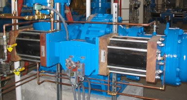
Vane actuator and dashpot assembly
Kinetrol vane actuator and
dashpot assembly
Water hammer occurs when the flow of fluid in a pipe rapidly changes. The result can be very high pipe pressures, mechanical stress on pipe supports, and possible reversal of flow. If not controlled it can cause pipe bursting, broken pipe supports and joint leakage.

The "hammering" is due to a pressure wave created by the instantaneous change in fluid velocity when a valve is suddenly closed or opened. Controlling valve closure time is one of the most economical ways to minimize water hammer. To do this efficiently, while still meeting the process requirements, the use of a variable speed mechanism to control valve stroke is used. One unique, economical and space savings approach is to use a pneumatic vane actuator coupled with a rotary damper (or dashpot).

Rotary dashpots are precision fluid damping devices which give a smooth resistance to shaft rotation which increases with angular velocity.

In this case, a pump station in the USA was having repeated problems with a large, open reservoir hydraulic actuator used to dampen valve opening and closing.  It was overly cumbersome and costly to maintain.

In its place, the pumping station installed Kinetrol Size 14 double acting actuators with digital speed controllers and Kinetrol LJ rotary dampers (with through-shafts to facilitate position feedback) installed on 12” Pratt butterfly valves.

The addition of the bi-directional, sealed dashpots smooth the normal travel, damp any valve flow induced disc oscillations, and provide at least 40 seconds travel time on air and/or electrical power failure.

Using pulsed outputs with programmable delay between steps, the actuators provide a 10 minute opening & closing time for the full 90 degree travel. The system is adjustable between 3-15 minutes with less than one degree increments., and other opening and closing ranges are available.  The actuators use fail-free logic, but fail-hold & fail-safe are available.

These assemblies were commissioned in early Fall of 2017 and are working very well. Their use will be replicated at other pump stations operated by the same customer.

open reservoir hydraulic actuator
This open reservoir hydraulic actuator was huge and a maintenance headache. 


Corrosive Flow Control Requirement? Use Thermoplastic Valves and Corrosion Resistant Rotary Actuators

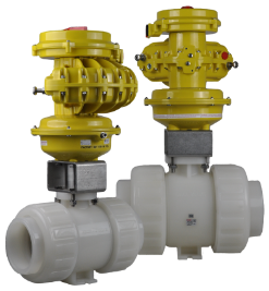
Thermoplastic valves
Thermoplastic valves with corrosion
resistant actuators, springs and positioners.
(Kinetrol)
Thermoplastic valves made of materials such as Polyvinyl chloride (PVC), Acrylonitrile-Butadiene-Styrene (ABS), Glass Fibre Polypropylene (GRPP), Anti-Static Polypropylene (ASPP), and Polyvinylidene fluoride (PVDF) are becoming the material of choice for more and more chemical process applications. Increasingly, you see these valves in industrial and commercial applications in pharmaceutical production, power generation, chemical processing, and water treatment. There reasons are obvious: chemical resistance; high purity standards; abrasion resistance; lighter weight; lower cost; and ease of installation.

Thoughtful actuator selection is required when plastic valves are specified. While the mechanics in applying pneumatic actuators to plastic quarter-turn valves is no different than metallic valves, the characteristics of the process and application can have significant impact on the performance the automated valve.

The assumption is that, if a thermoplastic valve is required, there is an higher probability the of exposure to corrosive media, or the automated valve assembly is located in a corrosive atmosphere, and therefore a corrosion resistant pneumatic actuator is preferred. Considering this, an actuator with internal and external parts protected by epoxy resins or special paints should be applied. Additionally, actuator spring systems should be designed in way to prevent exposure to corrosive media.
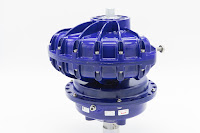
Corrosion resistant rotary vane actuator
Corrosion resistant
rotary vane actuator
with special external
coating. (Kinetrol Blueline).

The rotary vane actuators manufactured by Kinetrol standardly meet theses requirements. Engineered specifically for high-cycle, dirty, and corrosive applications, these very hardy, compact actuators come standardly with an epoxy stove enamel finish, stainless steel internal and external hardware, with spring units that are totally sealed from the atmospheric contaminants. For applications requiring greater corrosion resistance, such as caustic wash-down or salt-laden environments, an optional "Blueline" coating can be applied,

Happy New Year from Kinetrol USA!

All of us at Kinetrol USA wish our customers, distributors, colleagues and friends a very happy and prosperous 2018!


Kinetrol Blueline Pneumatic Actuator - Features

Features of the Kinetrol Blueline pneumatic actuator:
  • Durable Blueline coating meets FDA and BfR L1 specifications. 
  • Corrosion resistant zinc (non-incendive) or aluminum alloy case. 
  • Easy stop adjustment at each end of stroke for accurate seating. 
  • Long life epoxy or PTFE internal finish. 
  • Integral vane/shaft casting - only one moving part.
  • Manual override square and position indicator. 
  • Space filling/energy absorbent sideplates (polymer or metal). 
  • Double opposed, Polyurethane, lip seals for effective sealing and long maintenance free life.
  • Stainless steel expanders ensure long term lipseal / case contact


For more information, visit https://www.kinetrolusa.com/blueline

Kinetrol Actuator Feature Video

Here's a new Kinetrol vane actuator feature video. Please take a minute to watch. Hope you enjoy.