Wishing you and yours the happiest of holidays and a bright and successful New Year!
The Kinetrol rotary vane design is based upon a single moving part which eliminates additional parts required to convert linear motion to rotary motion. This simple and innovative design provides a highly accurate and extremely reliable actuator for operating valves, drives and dampers, and is perfectly suited for the most demanding process control applications. For more information visit www.kinetrolusa.com or call 972-447-9443.
Merry Christmas and Happy New Year from Kinetrol USA
In warm appreciation of our association during the past year, we extend our very best wishes for a happy holiday season.
Wishing you and yours the happiest of holidays and a bright and successful New Year!
Wishing you and yours the happiest of holidays and a bright and successful New Year!
The Toughest Pneumatic Actuators on Earth
Kinetrol's reputation for performing flawlessly in the harshest conditions is known around the world.
The Kinetrol vane actuators' outstanding cycle life, smooth and precise movement, and environmentally rugged design makes it the best choice for all of your valve actuation and damper drive requirements.
For more information visit http://www.kinetrolusa.com or call 972-447-9443.
The Kinetrol vane actuators' outstanding cycle life, smooth and precise movement, and environmentally rugged design makes it the best choice for all of your valve actuation and damper drive requirements.
For more information visit http://www.kinetrolusa.com or call 972-447-9443.
New Product: Kinetrol Model 15 Spring Unit in Male and Female Drive
Kinetrol has just released the new Model 15 Spring Unit which consists of a new single spring in a sealed, non-breathing housing, rather than the Model 15*-0*0-5900 which consists of two model 14 springs.
The new spring design has significant benefits including over a 30% reduction in weight, over 25% reduction in the axial dimension and an increase in the pressure range from 3.5 Bar to 5.5 Bar.
The spring unit is available in both male and female drive (F14 with a 36mm A/F female square) and will retrofit to all Model 15 Actuators.
A Basic Description of Valve Actuators
 |
| Automated plug valve with actuator, limit switch, and indicator. |
Some valves can be operated with hand wheels or levers, but some valves have to be open and closed or throttled frequently. Manually positioning valves in these types of situations is not always practical. So instead of hand wheels or levers, actuators are used to position the valves.
An actuator is a mechanism that moves or controls a device such as a valve. Actuators reduce the need for operators to go to every valve that needs repositioning and operate the valve by hand. When actuators are used, valves can be repositioned from a central remote location, such as a control room. This is very important in processes where a number of valves have to be repositioned accurately and quickly.
There are three basic types of actuators pneumatic actuators, hydraulic actuators, and electric actuators. Pneumatic actuators use air pressure to produce motion to position the valve. They're probably the most common type of actuator used in process systems. Actuators that are powered by a pressurized liquid, such as hydraulic fluid, are called hydraulic actuators. Compared to pneumatic actuators, hydraulic actuators of the same size are usually more powerful. Electric actuators use electricity to produce motion. They usually fall into one of two general classifications: solenoid actuators or motor-driven actuators.
Regardless of the type of actuator used with valves, actuators are normally part of process control systems. From a control room, valves with actuators can be quickly and accurately positioned to deal with frequent flow changes.
Valve actuators operate to position valves in response to signals from controllers. Controllers are part of the instrumentation systems that monitor plant processes and response to variations in the processes. Basically a controller is a device that receives an input from another part of the instrumentation system, compares that input to a set point, and sends out a corrective signal to regulate the value of a process variable such as temperature, pressure, level, or flow.
Generally, actuators are used with valves that are designed for throttling or regulating flow. Valves that are used to automatically throttle flow are generally referred to as control valves. However some on-off or isolation valves may also require actuators. Although these isolation valves may require actuators, they're not commonly referred to as control valves. Control valves can be either linear that is the stem moves the valve disc up and down as in globe and gate valves, or they can be rotary which means that they're positioned by rotation. Butterfly valves and ball valves, which open or closed with a 90-degree turn, are examples of rotary control valves.
Kinetrol Spring Return Units: Spiral Torsion Springs Are Key
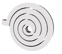 |
| Simple view of spiral torsion spring (protruding tab and hex center are loading points.) |
Capable of storing much more energy than a typical compression spring, and working in smaller, more compact packages, spiral torsion springs for valve and damper actuation are a proven step-up over helical compression springs.
When a torque is applied to a spiral torsion spring, an angular displacement is created between the first and second loading points, the coil deflects (tightens), and the spring material is placed under stress, exerting a linear (to the degree of rotation) rotational "output" torque, which drives the spring's rotation. Practically speaking, spiral torsion springs allow for lower torque loss, lower torque stress, and much greater reliability for use in valve and damper actuation.
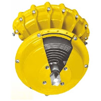 |
| Kinetrol Spring Return Unit (note cutaway revealing spiral torsion spring.) |
- Separate housing for modular assembly, easily retrofitted
- Sealed, non-breathing housing: Protects spring in corrosive environments
- Adjustable pretension for 'balanced' air and spring stroke torques: Various combinations available for balanced / optimized torques at various air pressures
- Keeper plates available to ensure safe handling of pretensioned springs
- Available with ISO/DIN female drive and mounting
The combination of the spiral torsion spring reliability plus the advanced engineering design allow Kinetrol to offer a guarantee against failure of the spring unit for the lifetime of the mating actuator!
For more information, contact Kinetrol USA by visiting www.kinetrolusa.com or calling 972-447-9443.
Review: Vane Actuators
 |
| An internal view of a vane actuator allowing you to see the one piece vane and shaft, lip seals, travel stops, and the clam shell design. |
The vane includes “lip seals” that isolate the vane and shaft from the air supply. The lip seal design provides several advantages, namely eliminating the need for shaft seals and an inherent cleaning action internally. A split, or “clam-shell” housing is assembled around the vane, totally enclosing it. When supply air is applied to one side of the vane, torque is produced moving the vane in one direction. Accordingly, there is direct rotary motion transfer to the shaft, with 100% efficiency. Torque is controlled by surface area of the vane and the differential pressure on either side of the vane. Bi-directional over-travel is limited by the use of travel stops mounted in both sides of the housing.
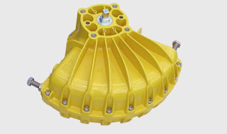 |
| The Kinetrol Vane Actuator |
For more information about vane actuators visit http://www.kinetrolusa.com or call 972-447-9443.
Actuator Sensor Interface for Kinetrol Vane Actuators
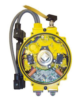 |
| Kinetrol AS Interface |
The slave devices will always function in response to commands sent by the master device, either to actuate, or to return a message reporting the value of a sensed variable, or both. The AS interface 2.1 specification allows 31 slave devices to be powered by a DC voltage fed into the same two-cable wire used as the communication bus, with allowed power consumption adequate to drive the slave plus a standard pneumatic solenoid valve. Under extended addressing, a maximum of 62 slave devices can be connected via one bus, but specified limits on device capacitance make this applicable only to systems with limited numbers of solenoid valves, or with a special scheme to get round the limit (see overleaf).
An AS interface bus can be used as the final field link in a more complex hierarchy of devices making up a large plant-wide control system. Actuators and sensors must often be installed in unprotected environments where conditions can be demanding; the AS interface bus is ideal for using as the link between these field devices and the “indoor” equipment making up the upper part of the control system.
AS interface is well suited to on/off control and monitoring, and is a good choice when a simple economical, reliable and robust solution is required to control and monitor a series of actuators and sensors in a process control or machine application. Kinetrol’s AS interface Universal Limit Switch Box is designed to meet all of these requirements.
The Kinetrol AS interface circuit board is fitted inside a standard actuator-mounted Kinetrol Universal Limit Switch Box (2 or 4 entry), so that the actuator (and up to 30 others like it) can be controlled, monitored and powered directly via a single two-conductor digital communication cable (or bus), using the open AS interface 2.1 standard. All the advantages of the limit switch box (all-metal construction, corrosion resistant, up to IP67 sealing, easy connection, easy setting of limit switch strikers etc - see KF487 literature) combined with the highly specified AS interface circuit to give unique levels of practicality, genuine industrial quality, and use-anywhere adaptability.
See thr full feature set and documentation below.
Why Vane Actuators Outlast and Outperform Rack & Pinion and Scotch Yoke Designs
 |
| Kinetrol vane actuators perform in the toughest applications. |
Kinetrol's design is based upon a single moving part, which eliminates additional parts required to convert linear motion to rotary motion. This simple and innovative design provides a highly accurate and extremely reliable actuator for operating valves, drives and dampers, and is perfectly suited for the most demanding process control control applications.
For more information, visit http://www.kinetrolusa.com
Need a Fail-Safe Valve Operator? Use This One.
 |
| Kinetrol manual fail-safe spring unit. |
These spring return units are designed to be put on valves to prevent, or limit, the impact of potentially hazardous accidents resulting from uncontrolled flowing fluid and gasses or spillage.
The Kinetrol manual fail-safe spring unit has a ISO/DIN female drive for direct mounting and ATEX category 2 options for use in hazardous areas. Kinetrol also offers a range of fire fail-safe spring assemblies that can be set to operate valves at pre-configured temperatures.
Because they cannot be left in the wrong position, they are commonly referred to as "deadman handles". Theses devices provide reliable torque delivery for valve reseating and come with completely sealed spring housings that meet IP65 levels, totally protecting the internal spring from the environment, making them ideal for outdoor applications.
Kinetrol FDA Approved Coating
 |
| Kinetrol actuator with FDA approved coating |
Products coated with Kinetrol RAL5002 Blueline food grade paint option, have a Kinetrol Variation Product Code: BU. This is suitable for use in the European Union & United States of America for Standard Actuators & Spring Units. For other assemblies including ULS and XLS switchboxes, AP, P3 and EL positioners a special order code will be issued.
For Example: a model 09 ISO Double acting Actuator having this coating would be: 094-100BU or model 09 ANSI Spring Return Actuator clockwise would be 097-120BU.
The product casings are pretreated prior to coating for additional protection. This coating system exhibits the following characteristics:
- Good resistance to 'caustic washdown' procedures as typically performed in the food industry.
- It shows exceptional resistance to chipping/flaking. It does not 'chip' in a brittle manner but remains attached to the substrate.
- If in extreme circumstances, the coating becomes dislodged from the product surface, its color is particularly visible to the human eye or sorters/sensors/detectors.
- Good resistance to corrosion in salt laden environments. 5. The coating has good non-stick properties.
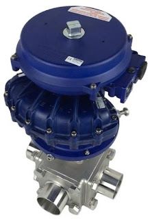 |
| Kinetrol Blueline coating now FDA approved. |
This coating is permitted for use in contact with food in compliance with the Federal Food, Drug and Cosmetic Act (FDA) and all applicable regulations, including 21 CR 175.300 (Code of Federal Regulations).
Coating Statement for European Union:
When coated in this finish, Kinetrol product casings meet the requirements of German BfR L1 for Temperature Resistant Polymer Coating Systems for Frying, Cooking and Baking Utensils. BfR recognizes that when in contact with food it will not transfer its constituents in quantities that could endanger human health.
When coated in this finish, Kinetrol product casings meet the requirements of German BfR L1 for Temperature Resistant Polymer Coating Systems for Frying, Cooking and Baking Utensils. BfR recognizes that when in contact with food it will not transfer its constituents in quantities that could endanger human health.
For more information on using Kinetrol actuators in food and pharmaceutical applications contact Kinetrol USA at www.kinetrolusa.com or call 972-447-9443.
Kinetrol P3 On/Off Positioner
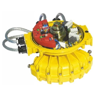 |
| Kinetrol P3 On/Off Positioner |
The Kinetrol P3 On/Off positioner consists of an electronic positioning circuit mounted in a robust all-metal enclosure, which controls a 1⁄4-turn rotary pneumatic actuator via standard on-off solenoid valves direct-mounted on the actuator’s own interface.
The P3 circuit is designed so that its assembly can be mounted inside a standard Kinetrol limit switch box (either ULS-type, or explosion proof XLS-type), using only two screws. The P3 assembly is complete with feedback potentiometer and anti-backlash gear drive, which engages with gear teeth on the limit switch coupling to read the actuator’s position. The limit switch coupling complete with gear teeth needs to replace the standard coupling if a standard box is being retrofitted with a P3.
The positioner circuit is powered by the mid-point input voltage. It functions by comparing the actual mid-point position (read by the feedback potentiometer) with the set position (set via an on-board preset, or a remote preset, or a remote 4-20mA signal). The positioner circuit uses its solid-state switched outputs to power solenoid valves which drive the actuator towards the position where the set position corresponds with the actual position. When it gets there, the solenoids are switched to hold that position.
The positioner circuit incorporates a unique power supply allowing it to be powered by any of 24vDC, 48vDC, 115vAC or 230vAC, 50/60 Hz, without the need for any change. The supply maintains full isolation of the low voltage control circuit from the power input line (up to 5Kv). Switching of the solenoid valve outputs is achieved through opto-isolated solid state switches which operate at all the above voltages – only the solenoid coils themselves need to be adapted specifically to the supply voltage. The use of solid state switching avoids any limitations on relay contact life.
Double acting models are available as fail-free (standard), fail-down (moves clockwise on loss of electrical power if air supply is still present) and fail-hold (holds position on loss of electrical and / or air supply) variants. Spring return models move in the direction of the spring on loss of electrical failure, but hold position on loss of air. An external pressure switch (which cuts electrical power on loss of air pressure) should be fitted by the customer if spring function is required on loss of air and / or electrical power.
An optional angle retransmit (AR) circuit can be retrofitted by plugging it into the top of the positioner circuit and fixing with three screws. The AR circuit is a 2-wire loop-powered 4-20mA device, which reads the position of the positioner’s feedback pot. It is fully functional whether or not the positioner circuit is powered, and the feedback signal is electronically isolated (ie. floating) relative to the low voltage positioner circuit (which in turn is electrically isolated from the power supply and solenoid connections).
Extra solid-state switches have been incorporated on the positioner board to allow supply to both solenoid valves via a single cable for movement to the upscale position when the positioner is in spring-return or fail-down mode, while still allowing the positioner to control the two valves independently for the mid position. If the mid-position input is energised, then these extra switches isolate the solenoids from the upscale/downscale inputs.
The three power input lines (for up, mid, down positions) are independently fused using plug-in miniature fuses on the positioner circuit board.
External connections are made via a multi-option connector board, which allows simultaneous connection of up to four changeover limit switches, three control supply inputs plus neutral/negative, and a single low-voltage signal. This connector board, like the positioner circuit assembly, mounts in either the standard ULS or XLS box using two screws.
If an angle retransmit circuit is fitted using the low voltage signal terminal, optional 4-20mA inputs or external setpoint pot wires can be connected either directly to the terminal block on the positioner circuit or, if only three or less limit switches are in use, relayed through an unused limit switch terminal on the connector board.
The limit switch box is fitted with a ground terminal which must be connected to a suitable external ground.
Industrial solenoid valves which permit the use of standard quality air supplies (instrument quality air is not required) are direct-mounted on adaptor blocks on the side of the actuator, and electrically connected via steel-armoured flying leads with DIN sockets on the solenoid end. At the positioner end, they connect to two 2-way terminal blocks on the circuit board. A range of solenoid valve options are available, determined by the function required, the supply voltage, and whether or not the unit requires hazardous area certification.
The positioner circuit is powered by the mid-point input voltage. It functions by comparing the actual mid-point position (read by the feedback potentiometer) with the set position (set via an on-board preset, or a remote preset, or a remote 4-20mA signal). The positioner circuit uses its solid-state switched outputs to power solenoid valves which drive the actuator towards the position where the set position corresponds with the actual position. When it gets there, the solenoids are switched to hold that position.
Need More Information?
Contact Kinetrol USA at
or call 972-447-9443.
The positioner circuit incorporates a unique power supply allowing it to be powered by any of 24vDC, 48vDC, 115vAC or 230vAC, 50/60 Hz, without the need for any change. The supply maintains full isolation of the low voltage control circuit from the power input line (up to 5Kv). Switching of the solenoid valve outputs is achieved through opto-isolated solid state switches which operate at all the above voltages – only the solenoid coils themselves need to be adapted specifically to the supply voltage. The use of solid state switching avoids any limitations on relay contact life.
Double acting models are available as fail-free (standard), fail-down (moves clockwise on loss of electrical power if air supply is still present) and fail-hold (holds position on loss of electrical and / or air supply) variants. Spring return models move in the direction of the spring on loss of electrical failure, but hold position on loss of air. An external pressure switch (which cuts electrical power on loss of air pressure) should be fitted by the customer if spring function is required on loss of air and / or electrical power.
An optional angle retransmit (AR) circuit can be retrofitted by plugging it into the top of the positioner circuit and fixing with three screws. The AR circuit is a 2-wire loop-powered 4-20mA device, which reads the position of the positioner’s feedback pot. It is fully functional whether or not the positioner circuit is powered, and the feedback signal is electronically isolated (ie. floating) relative to the low voltage positioner circuit (which in turn is electrically isolated from the power supply and solenoid connections).
Extra solid-state switches have been incorporated on the positioner board to allow supply to both solenoid valves via a single cable for movement to the upscale position when the positioner is in spring-return or fail-down mode, while still allowing the positioner to control the two valves independently for the mid position. If the mid-position input is energised, then these extra switches isolate the solenoids from the upscale/downscale inputs.
The three power input lines (for up, mid, down positions) are independently fused using plug-in miniature fuses on the positioner circuit board.
External connections are made via a multi-option connector board, which allows simultaneous connection of up to four changeover limit switches, three control supply inputs plus neutral/negative, and a single low-voltage signal. This connector board, like the positioner circuit assembly, mounts in either the standard ULS or XLS box using two screws.
If an angle retransmit circuit is fitted using the low voltage signal terminal, optional 4-20mA inputs or external setpoint pot wires can be connected either directly to the terminal block on the positioner circuit or, if only three or less limit switches are in use, relayed through an unused limit switch terminal on the connector board.
The limit switch box is fitted with a ground terminal which must be connected to a suitable external ground.
Industrial solenoid valves which permit the use of standard quality air supplies (instrument quality air is not required) are direct-mounted on adaptor blocks on the side of the actuator, and electrically connected via steel-armoured flying leads with DIN sockets on the solenoid end. At the positioner end, they connect to two 2-way terminal blocks on the circuit board. A range of solenoid valve options are available, determined by the function required, the supply voltage, and whether or not the unit requires hazardous area certification.
KEY FEATURES
- Robust modulating actuator, control tolerant of standard air quality (instrument air quality is not necessary).
- Three position rotary control using only three electrical inputs plus air supply.
- Two endstop positions + adjustable mid position anywhere in angular range of actuator (90 or 180°).
- Control circuit mounts inside standard all metal industrial quality Kinetrol ULS or XLS limit switch boxes without disturbing limit switches – available fully assembled, or (on non-explosion proof models only) for user retrofit to existing boxes.
- Direct mounting onto full range of Kinetrol 1⁄4 turn actuators. Namur mounting options available.
- Uses direct-mounting standard solenoid valves outside box to position actuator.
- Easy adjustment of mid position set point by switch–selectable choice of methods: on-board pot, remote pot or 4-20mA input signal.
- Explosion proof options available (approved to IECEX, ATEX; FM (for USA & Canada) standards pending) by use of XLS housing plus standard explosion proof solenoid valves.
- All new positioner circuit – runs on any of 24vDC, 48vDC, 115vAC or 230vAC power without any change required.
- Solid-state universal-voltage solenoid switching – no mechanical contacts.
- Three separate on-board mains fuses for three inputs.
- Switchable selection of mid-point setting method (on-board preset, remote preset, remote 4-20mA signal).
- Switchable selection of double acting or spring return operating mode.
- Power input isolated from signal inputs and outputs for all voltage options.
- Moulded reinforced plastic internal circuit cover for insulated safety.
- Positioner has user-adjustable zero, span, deadband and damping parameters via preset pots for easy optimization of positioning performance.
- Damping parameter gives velocity-proportional setpoint advance to allow better stabilization of fast-moving or high inertia loads while maintaining resolution and repeatability.
- Retrofittable isolated loop-powered 4-20mA angle-retransmit circuit available – just plugs in inside same enclosure – with its own user-adjustable zero and span presets.
Need More Information?
Contact Kinetrol USA at
www.kinetrolusa.com
or call 972-447-9443.
Valve Actuators for Bottom Ash High Pressure Spray Removal
 |
| Coal burning power plant |
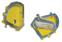 |
| Kinetrol Rotary Vane Actuator |
Its crucial that the double offset valves seat completely and are truly “zero-leakage”. In this high pressure and high abrasion scenario, even the slightest leak will cause a rapid failure of the valve seat.
Rack and pinion, scotch yoke, and electric actuators are problematic because of the inherent hysteresis in their gearing. This hysteresis compounds over time adding to the amount of error introduced and increasing the likelihood of a poorly closed valve.
Rotary vane actuators, on the other hand, provide “hysteresis-free” seating due to their single moving part and one piece vane and shaft design. When mounted to the butterfly valves with a no-play coupler, the valve disc is guaranteed to close tightly, without degradation over time.
Additional benefits of using the vane actuator is smooth, controlled closing to reduce the possibility of water hammer and the greater ability work in poor quality atmospheres, both of which are considerations for this application.
Cement Silos Need Valve Actuators with Power and Reliability
 |
| Kinetrol spring return actuator on cement silo valve. |
One particular cement processing plant needed a replacement for their main silo off loading valves. These valves fill cement trucks the company used to deliver their product.
The plant's existing valves were poorly applied for this use and were causing major headaches. The valves were designed with thin steel plate, large gaps between the valve body and disc, and rubber seals that wore away, leading to cement leaking through the valve. The leaking cement would spill onto a feed trough where it would cake and require manual cleaning - an expensive and time consuming operation. If the valve didn’t leak, this expense and time would be saved.
A custom valve manufacturer was called in to use their engineering and fabrication expertise to develop a custom valve that would last. The result was a new rotary valve that uses a much hardier wear plate, and the rotor and body are carefully machined with only a 2/100ths of an inch gap between them. Additionally, the design provides a mechanism to catch any cement should any ever make it through the gap.
The new, custom designed valve needed an actuator that would be equally reliable. The selection of Kinetrol vane actuator with a spring return was the most obvious because its power and its reliability. With only one moving part and no complex linkage to wear out, it was the best choice for long life. The combination of valve and actuator is expected to last many thousands of operations with no maintenance.
Procedure for Calculating Distance of Actuator from Hot Valve
The purpose of this post is to assist in determining the proper distance of a Kinetrol actuator from a hot valve.
In many situation, valves are put inline with a hot process media flowing through the piping system. In these situations, careful consideration must be taken to avoid over temperature exposure of the Kinetrol actuator via conductive or radiant heat.
The following formulae will assist in giving you data to calculate the safe distance between hot valve and actuator.
If you need assistance, or have any concerns about properly distancing the actuator from your process, it's always best to consult with the experts at Kinetrol USA. They're just a phone call away. For more information visit www.kinetrolusa.com or call 972-447-9443.
In many situation, valves are put inline with a hot process media flowing through the piping system. In these situations, careful consideration must be taken to avoid over temperature exposure of the Kinetrol actuator via conductive or radiant heat.
The following formulae will assist in giving you data to calculate the safe distance between hot valve and actuator.
For steel RHS mount kits, standard (80°C Max.) actuators
In ambient 50°C air.
Kinetrol EL Positioner Option: Special Characteristic for Butterfly Valve Linear Flow Control
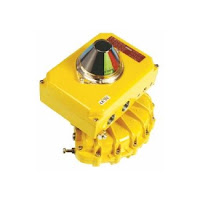 |
| EL Positioner |
EL positioner option: Special characteristic to give butterfly valve control for linear valve flow vs. input signal.
Upon request Kinetrol can supply a positioner fitted with a circuit that will provide an output characteristic to suit a butterfly valve. By replacing the standard circuit (with 10 non-linear and one linear control response curves) by one containing a microprocessor programmed with 10 different non-linear curves and one linear, the valve can be controlled to give optimum flow control with a butterfly valve.
In general the pressure drop across a valve will change as the valve opens, and this changes the flow/valve position characteristic. The five solid line curves on the graph linearise the response for valve pressure drops which fall to a range of values as the valve is opened fully, see below.
The values below are the pressure drop with the valve full open expressed as a percentage of the pressure drop with the valve closed.
A butterfly valve controlling the flow of a fluid with a 10% constant pressure drop, gives 50% of its fully open flow at an angle of opening of roughly 40 degrees. We would thus recommend the user set the control response to curve -3, here 12mA (half signal) would open the valve to 40 degrees to allow 50% flow rate. The user can select one of the eleven pre-programmed curves by going into SETUP mode.
- Curve -1 for 100% (this should be used to linearize a butterfly valve which is operating with a constant pressure drop)
- Curve -2 for 30%
- Curve -3 for 10%
- Curve -4 for 3%
- Curve -5 for 1%
Click on graph for larger view.
Example
A butterfly valve controlling the flow of a fluid with a 10% constant pressure drop, gives 50% of its fully open flow at an angle of opening of roughly 40 degrees. We would thus recommend the user set the control response to curve -3, here 12mA (half signal) would open the valve to 40 degrees to allow 50% flow rate. The user can select one of the eleven pre-programmed curves by going into SETUP mode.
Labels:
butterfly control valve,
EL,
Kinetrol,
linear output,
valve positioner
Kinetrol + Plug Valve = Optimum Sludge Valve Performance
 |
| Water treatment plant |
Many valve manufacturers specify high-pressure/high-torque actuators to overcome the sludge. Many times they choose linear type valves and screw-type linear actuators because they provide the brute force needed to push through the sludge. An unwanted side-effect of using linear valves and actuators is that the same force used to push the disc through the sludge, also causes valve damage by pushing and grinding solids into the valve seats, disc and seals. Eventually, the valve becomes so damaged it no longer provides proper shut-off.
 |
| Kinetrol actuator |
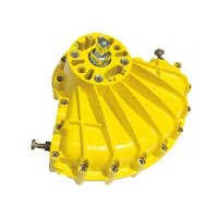
For sludge applications, Kinetrol rotary vane actuators mounted on quarter-turn plug valves are a great choice . The combination of the high cycle actuator design, with the design benefits of a plug valve, offer wastewater treatment operators a valve assembly that will provide years of trouble-free life.
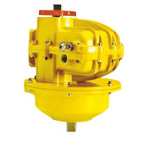
Kinetrol Series 180 - 189 Actuator Spring Removal Replacement Instructions
 |
| Kinetrol Spring Return Actuator |
For more information, visit www.kinetrolusa.com or call 972-447-9443.
Fit and Forget, Worry-free Pneumatic Valve Actuators
Here's a short, narrated introduction to the Kinetrol vane actuator and their use on industrial valves. Kinetrol's 60 years of applying "fit & forget, worry about something else" actuators has rightfully earned their reputation for being the most durable, long-lasting valve actuator on the market today - a statement backed by a 4 million cycle warranty and documented, real-world field installations where the actuator provided upwards of 30 million maintenance-free cycles.
For more information, visit http://www.kinetrolusa.com.
For more information, visit http://www.kinetrolusa.com.
What Is a Vane Actuator?
 |
| Inside view of a vane actuator showing the clam-shell design, internal chamber layout, and double-sided vane. |
Linear motion gas/hydraulic cylinder or piston actuators use gears to convert linear to rotary motion. Vane actuators employ a rigid vane inside a sealed chamber that is connected directly to the drive shaft at one end with no gears. The result is much smoother rotary movement and greater cycle life.
Vane actuators operate by introducing a fluid or gas to either side of it's enclosure through inlet/outlet ports, creating the force required for movement. Advanced vane actuators utilize double sided vanes that allow for pressurization of both sides, allowing for bi-directional movement. The vane itself provides an arc movement in the far side (opposite the shaft) of the actuator, translating rotary movement back to its integrated shaft.
The vane actuator shaft is designed to connect directly to a device (valve, damper, ergo mechanism) for the transfer of movement. In advanced design vane actuators, the shaft is completely sealed from the pressurized side of the vane via “lip seals” which act to prevent the loss of air/gas/oil through shaft seals or bearings. With the help of spring steel supports, the lip seals are kept in constant contact with the inner surface of the chamber wall at all times during rotation. A side benefit of lip seals are the self-cleaning or sweeping action they provide to the inside chamber surfaces.
Since the double-sealed vane separates the vane actuator chamber in two sides, movement in either direction can be changed merely by creating a pressure differential on either side of the vane. Inlet/outlet ports allow for the pressurization and de-pressurization for either side. As gas or fluid is introduced to one side, the vane is forced away, toward the opposite side. By reversing the pressure and vent ports, and pressurizing the opposite chamber, the actuator moves in the opposite direction.
When vane actuators use only gas or fluid as their source for movement in both directions, they are referred to as “double acting”. When an optional spring is used to provide the power in one direction (open or close) they are referred to as “spring return”.
For more information on vane actuators, visit http://www.kinetrolusa.com
Kinetrol Clear Cone Monitor & Solenoid Valve Cut Sheet
The optional Clear Cone provides all round high
visibility position monitoring on all limit switch boxes
and positioner models. A red/green colour coded
monitor is sealed inside a robust, clear polycarbonate
cover. Positioner models are marked with black printed
legible angle scales.
As an option Kinetrol actuator sizes 03 to 15 can be supplied with integral solenoid valves with NAMUR interface. Air is ported through the actuator body via an adaptor so no external tubing is necessary
See the full cut sheet below:
As an option Kinetrol actuator sizes 03 to 15 can be supplied with integral solenoid valves with NAMUR interface. Air is ported through the actuator body via an adaptor so no external tubing is necessary
See the full cut sheet below:
Vane Actuators Perform Better: Its All About the Gears (or Lack Thereof)
 Why do vane actuators consistently outlast rack and pinion and scotch yoke actuators? The truth is in the gears.
Gears wear.
 Surface wear, contact fatigue, scuffing and tooth bending are all real-life issues when dealing with gears. Surface wear affects gear contact in such a way that accelerates failure modes by increasing contact stresses and load distributions. This always leads to reduced accuracy and loss of smooth operation. Wear can never be completely eliminated, and over time, progresses at a more rapid rate.
 |
| Typical rack and pinion design - note gear arrangement |
- Sliding stress - causes surface fatigue damage.
- Rolling stress - causes contact fatigue damage.
- Bending stress - like a cantilever beam, always deforms.
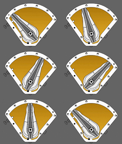 |
| Vane actuator - no gears |
Pure simplicity - the rotary vane.
One moving part. No gears.
The rotary vane actuator design is based upon a single moving part which eliminates gears required to convert linear motion to rotary motion. This simple and innovative concept provides an extremely reliable mechanism for operating valves, drives and dampers.
More Accurate Control
Another advantage rotary vane actuators have over rack & pinion and scotch yoke actuators is in smoothness and accuracy of control. The more mechanical connections the actuator has, the greater the cumulative hysteresis, and the lower the control responsiveness and accuracy.
For long, trouble-free performance, choose a rotary vane actuator for your next valve actuation or damper drive requirement. You'll be very glad in the long run.
For long, trouble-free performance, choose a rotary vane actuator for your next valve actuation or damper drive requirement. You'll be very glad in the long run.
The ISO 5211 Valve Mounting Flange and Actuator Connection
 |
| Valve with ISO 5211 Flange |
A standard interface between actuator, valve, solenoids, and positioners provides many benefits. Actuated valve assemblies are installed in a very wide range of applications and operating conditions resulting in many custom designs. Understanding the connection between these components is critical for long life, safety, and performance.
A standard mounting / connecting device lowers inventory costs and allows for faster maintenance and repair. Standardization also allows for the replacement of brands, so long as both adapt to the standard. Finally, using industry standard adapters maintain consistent specifications and tolerances which improve performance by reducing hysteresis and mechanical wear.
Kinetrol manufactures an ISO adapter for its models 02, 03, 05, 07, 08 and 09 which allows for mounting ISO 5211 valves directly to standard Kinetrol double acting actuators.
For more information about Kinetrol's ISO adapter, please review the document below.
Hear Kinetrol USA's Neil Meredith Interviewed at WEFTEC 2016
 |
| Neil Meredith |
WEFTEC®, the Water Environment Federation’s Annual Technical Exhibition and Conference, is the biggest meeting of its kind in North America and offers thousands of water quality professionals from around the world the best water quality education and training available today. Also recognized as the world’s largest annual water quality exhibition, WEFTEC’s massive show floor provides unparalleled access to the field’s most cutting-edge technologies and services.
Kinetrol actuators are widely used in municipal water systems across the United States and are known for their outstanding performance, durability, and extreme high cycle life.
New YouTube Channel Welcome Video
Kinetrol USA is reorganizing and updating its YouTube Channel. Here is the new Welcome video for the channel.
To see all Kinetrol YouTube videos visit https://www.youtube.com/c/Kinetrolusa1
To see all Kinetrol YouTube videos visit https://www.youtube.com/c/Kinetrolusa1
Installation, Operation & Maintenance Instructions for Kinetrol Rotary Actuator: Double Acting & Spring Return Models
 The Kinetrol rotary vane actuator is based upon a single moving part that converts linear motion to rotary motion. Since 1958 it has been a true workhorse solving the most demanding valve actuation applications. Millions of actuators are used around the world operating valves, drives and dampers with flawless performance.
As a matter of convenience and support, we are posting the general Kinetrol actuator IOM here for future reference.
Warehouse Palletizers Rely on Kinetrol Actuators for Trouble-free Performance
 |
| Palletizer gripper head with Kinetrol actuator |
 |
| Palletizer with Kinetrol Actuators |
One component is the palletizer subsystem. The palletizer subsystem provides automatic stacking of products on top of a pallet.
More sophisticated palletizers have complex control systems to provide the speed, accuracy and control required for large scale operation. The control systems are made up of computers, PLCs, proximity devices, and optical instruments. For product movement, transfer, and placement, palletizers rely on highly accurate pneumatic, electro-pneumatic, and electro-hydraulic motors, actuators, and drives.
 |
| Palletizer in plant. |
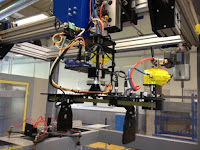
Because of their high cycle life, smooth movement, precise control, and maintenance free operation, Kinetrol vane actuators have been very successfully used by palletizer OEMs. The actuator provides 90 degree and 180 degree rotation on the vacuum gripper head and pivot arms. During normal operation the Kinetrol actuators can see upwards of 20,000 cycle per day.
For more information on applying Kinetrol vane actuators to your packaging systems, contact:
Kinetrol USA
1085 Ohio Drive
Plano, Texas 75093
www.kinetrolusa.com
(972) 447-9443 phone
(972) 447-9720 fax
Tighter Boiler Emissions Control with Pneumatic Vane Actuator Damper Drives
 |
| Pneumatic rotary vane damper drive. |
In order to ensure efficient, reliable, and safe boiler operation, it is critical to accurately control the flow of the boiler's combustion air and flue gas. Poor control of airflow results in inefficient burning (wasting money), erratic cycling, flame-outs and even the possibility of toxic and hazardous emissions. In order to reduce the likelihood of these situations, accurate airflow control is critical.
In the United States, the Environmental Protection Agency's introduction of the MACT (Boiler Maximum Achievable Control Technology) Rule requires operators to institute maintenance procedures annually or bi-annually in an effort to force plant operators toward compliance. This strict new legislation has a large impact on how companies' control their emissions from industrial boilers, process heating systems and furnaces.
 |
| Typical drive applications and designs (click for larger picture). |
Industrial boilers use dampers and louvers to control the quantity of air admitted to the furnace. Tighter boiler draft control significantly improves combustion. Any improvement in controlling the position of the dampers and increasing the positioning speed improves boiler efficiency. Damper operation needs to be precise and fast for the accurate control.
There are an estimated 15,000 boilers, furnaces, and process heaters running in the USA, and many are using an outdated primary component to control their lovers and dampers - the electric damper drive. Electric damper drives utilize motors and gear-boxes to move and position flue gas and combustion gas dampers. However, because of the inherent movement (sometimes referred to as hysteresis) between gears, linkages and other assorted mechanisms, these drives may not provide the accuracy, power, or signal response time required for optimum control.
Enter the pneumatic vane actuator damper drive. Pneumatic vane actuator drives are a newer, but still proven, method to provide high speed, accurate, and continuous modulation of air dampers for precise control. Replacing outdated electric damper drives with fast acting, pneumatic rotary vane damper drives offers measurable improvement to burner efficiency and cleaner emissions.
Switching out electric drives with their better performing pneumatic cousins is fairly simple. Downtime is not an issue. The old drive footprint, lever positions, connecting rods, and operational envelop are considered with every design. Any existing mechanical or electrical connection placements are matched. Since the new drive mates to all existing mounting and connections, and the envelope size is typically smaller, installing the pneumatic drive is usually a matter of pulling the old one out, and dropping the new one in.
At the heart of the pneumatic damper drive is the stalwart pneumatic rotary vane actuator. With hundreds of thousands of these devices operating in the toughest process applications around the world, their reputation is well earned. These actuators are known for their incredibly long life, ability to withstand very high cycle rates, and smooth “bump-less” control. They are also designed to handle high ambient temperatures, high vibration, and very dusty environments, typical of where boiler dampers are located. Additionally, rotary vane actuators are available with direct mount pneumatic and electro-pneumatic positioners, manual overrides, network communication modules, limit switches, and spring modules. The direct mount design eliminates external brackets and coupling, and keeps the overall package size small.
Pneumatic vane actuator damper drives are a significant improvement over traditional electric damper drives. They provide fast response to input signal changes, very accurate positioning, a reduction in plant air consumption, and they lower fuel consumption. Engineers tasked with increasingly rigorous boiler emissions requirements must consider pneumatic vane style drives as a compelling alternative to the electric drive. They truly are an example of better form, fit, and function.
Labels:
boiler,
damper,
Damper Drive,
emissions,
Kinetrol,
louver,
MACT,
Vane Actuator
Bulk Material Handling Diverter Valves Choose Vane Actuators for Reliability and Compactness
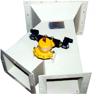 |
| 2-Way Diverter with Kinetrol Actuator |
 |
| Dense Phase 2- Way Diverter with Kinetrol Actuator |
The durability of the vane type pneumatic actuator, along with its compact design and simplicity, continues to win over the hearts and minds of diverter valve manufacturers. The vane actuator's reliability is attributed to one significant advantage over rack & pinion, piston, and scotch yoke actuators - the vane actuator has only one moving part.
Not all vane actuators are created equal however. Some manufactures have compromised their performance and reliability by taking design short-cuts, such as eliminating high quality coatings, and eliminating important features, such as high tolerance machining and stainless steel internals.
 |
| Stainless Steel 2-Way Diverter with Kinetrol Actuator |
Spring Return "Deadman" Handles: Certainty of Valve Position When Unattended
 |
| Spring Return Handle on Ball Valve |
This uniquely designed manual operator offers some compelling advantages in automating valves and provides additional levels of plant safety.
Spring return (also known as "deadman") handles will help you meet individual plant safety requirements as well as and OSHA requirements for valves that must return to the closed position after operation. Different from lever handle or gear operators which will leave the vale in the last position, the spring return deadman device ensures that the handle will always be driven to its original starting position by the associated spring.
Unique Features Include:
- Manual unit cannot be left in the wrong position
- Reliable torque delivery for valve reseat
- Fire fail-safe option, for fail-safe manual operation of valves
- Clockwise or counter clockwise 90° spring action
- Spring housing sealed to IP65 to protect from internal corrosion
- ISO5211 female drive & ATEX Category 2 approved options available forKinetrol actuators 02, 03, 05 and 07
Troubleshooting & Set Up Guide for Kinetrol EL Positioners
 |
| Kinetrol EL Positioner |
In terms of response and accuracy, the EL Positioner is arguably one of the best electro-pneumatic positioners in the world, particularly when used in tandem with a Kinetrol vane actuator.
The document below provides an illustrated troubleshooting and set-up guide for the EL electro-pneumatic positioner and is available to support the all the units installed in chemical, petro-chemical, water treatment, power generation and other applications across the world.
Superpulsator Vent Valve Operation Demands Performance
 |
| Kinetrol on Superpulsator Vent Valve |
A Superpulsator unit is a simple type of clarification system utilizing an upward flow tank and inclined plate settling. It operates by varying the level of the flocculation tank through the use of a vacuum pump and vent valve. The pump creates a vacuum in the tank causing the water level to rise. A vent valve then opens to atmosphere causing the water level to fall. The valve is then closed, and the process repeats itself continuously. The actuated vent valve is controlled by a timer set to pre-defined vacuum and vent cycles.
A Kinetrol USA Distributor was called in to assist in a water treatment plant’s upgrade to superpulsators. After reviewing the application, the Distributor specified 4" plug valves actuated with Kinetrol vane actuators and Kinetrol ULS limit switches. The plant’s original system was using double acting, air cylinder operated valves. These had to be replaced because they wouldn't be able to withstand the superpulsator's constant vacuum and venting cycling. The more robust Kinetrol actuator, capable of very high cycle rates, was clearly the best choice.
After installation and startup, and several years in operation, the Kinetrol actuators are performing flawlessly and are providing maintenance-free operation.
Subscribe to:
Comments (Atom)


